


6-24
Cisco ASR 1000 Series Aggregation Services Routers Hardware Installation and Initial Configuration Guide
OL-13208-03
Chapter 6 Cisco ASR 1002 Router Overview and Installation
Attaching a Chassis Ground Connection
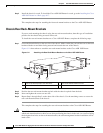
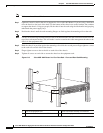
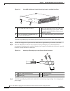
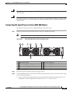
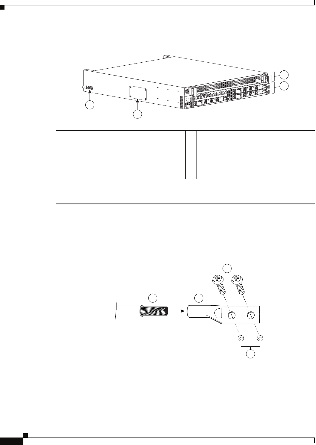
Figure 6-15 Cisco ASR 1002 Router Chassis Ground Lug Location and Side Panel Door
To attach the grounding lug to the chassis ground connector on your chassis, follow these steps:
Step 1 Use the wire stripper to strip one end of the AWG #6 wire approximately 0.75 inches (19.05 mm).
Step 2 Insert the AWG #6 wire into the wire receptacle on the grounding lug. Use the manufacturers’s
recommended crimping tool to carefully crimp the wire receptacle around the wire; this step is required
to ensure a proper mechanical connection.
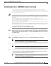
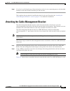
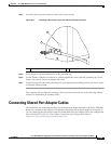
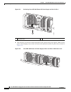
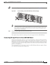
Figure 6-16 Attaching a Grounding Lug to the Chassis Ground Connector
Step 3 Attach the grounding lug with the wire on the left to avoid having the grounding wire overlapping the
power supply.
AS
R
1
002
s
t
a
t
pw
r
m
i
n
m
a
j
c
r
it
S
P
A
-
4
X
O
C
3
-
P
O
S
S
T
A
T
U
S
0
1
2
3
C
/A
A
/
L
C
/A
A
/
L
C
/A
A
/
L
C
/A
A
/
L
S
P
A
-
4
X
O
C
3
-
P
O
S
S
T
A
T
U
S
0
1
2
3
C
/A
A
/
L
C
/A
A
/L
C
/
A
A
/L
C
/A
A
/L
ST
A
T
QE
0
Q
E
1
QE
2
QE
3
BO
O
T
C
ARR
I
E
R
L
I
N
K
P
W
R
S
T
A
T
MT
S
MG
MT
A
U
X
C
O
N
SP
A
-
4
X
O
C
3
-
P
O
S
S
TAT
U
S
0
1
2
3
C
/
A
A
/L
C
/A
A
/L
C
/A
A
/L
C
/
A
A
/L
3
1
2
4
280283
1 F0 with ASR1000-ESP5 or ESP10. 3 The eUSB panel door on the side of the Cisco
ASR 1002 Router must not be opened. If there
is a problem with eUSB flash card, the chassis
should be returned.
2 R0 slot with embedded ASR1000-RP1 and
embedded ASR1000-SIP10.
4 Cisco ASR 1002 Router ground stud location.
1 Chassis ground connector holes 3 Ground lug screws
2 Grounding lug 4 Ground wire
50536
1
2
3
4