


6-25
Cisco ASR 1000 Series Aggregation Services Routers Hardware Installation and Initial Configuration Guide
OL-13208-03
Chapter 6 Cisco ASR 1002 Router Overview and Installation
Connecting Shared Port Adapter Cables
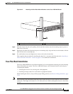
Step 4 Locate the chassis ground connector on the side of your chassis.
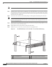
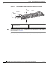
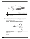
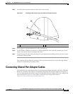
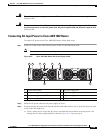
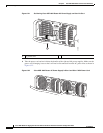
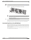
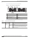
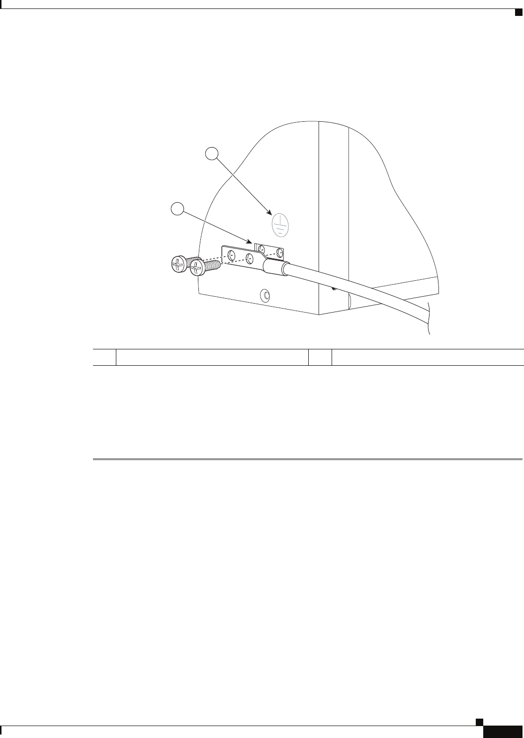
Figure 6-17 Attaching a Grounding Lug to the Chassis Ground Connector
Step 5 Insert the two screws through the holes in the grounding lug.
Step 6 Use the Number 2 Phillips screwdriver to carefully tighten the screws until the grounding lug is held
firmly to the chassis. Do not overtighten the screws.
Step 7 Connect the opposite end of the grounding wire to the appropriate grounding point at your site to ensure
an adequate chassis ground.
This completes the procedure for attaching a chassis ground connection. Go to the following cabling
sections for information on attaching cables.
Connecting Shared Port Adapter Cables
The instructions for connecting the cables for the shared port adapter installed in the Cisco ASR 1002
Router are contained in the respective configuration documents for each port adapter. For example, if
you are connecting the optical fiber cables for the PA-POS-OC3 port adapter, refer to the configuration
note PA-POS-OC3 Packet OC-3 Port Adapter Installation and Configuration Guide at
http://www.cisco.com/univercd/cc/td/doc/product/core
1 Chassis ground connector 2 Earth ground symbol
280284
1
2