


5-23
Cisco ASR 1000 Series Aggregation Services Routers Hardware Installation and Initial Configuration Guide
OL-13208-03
Chapter 5 Cisco ASR 1004 Router Overview and Installation
Connecting Power to Cisco ASR 1004 Router
This section provides the procedures for connecting AC-input and DC-input power to your
Cisco
ASR 1004 Router.
The DC power supply for the Cisco ASR 1006, ASR 1004, and ASR 1002 routers operate at individual
specifications.
Table 5-2 shows the common input ranges and circuit breaker requirements.
Note All Cisco ASR 1000 Series Router AC power supplies require a 20 AMP circuit breaker.
Note Detailed instructions for removing and replacing the Cisco ASR1000 Series AC and DC power supplies
are in Chapter 8, “Replacing Cisco ASR 1000 Series Routers Field-Replaceable Units.”.
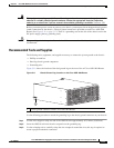
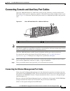
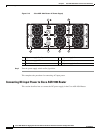
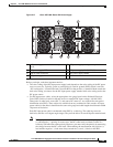
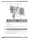
Connecting AC-Input Power to Cisco ASR 1004 Router
Follow these steps to connect an AC-input power supply to the Cisco 1004 chassis:
Step 1 Insert an AC power supply in power supply slot 0 or power supply slot 1 until it is fully seated.
Step 2 Tighten the captive screws.
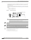
Step 3 Insert the AC power cable into the power inlet.
Step 4 Plug the power supply cable into the power source.
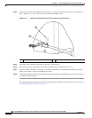
Note For additional AC power cable strain relief, secure the cable to the power supply handle by
inserting a nylon cable tie through the hole in the handle and around the cable.
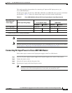
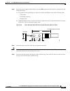
Table 5-2 Cisco ASR 1000 Series Router DC Power Supply System Input Requirements
Cisco ASR 1000
Series Router DC
Power Supply
System Input Rating (Amps) Circuit Breaker Amps AWG # Wire
Minimum Maximum Minimum Maximum
Cisco ASR 1006 40 Always 50 Always AWG #6 wire
Cisco ASR 1004 24 30 40 10 8
Cisco ASR 1002 16 20 30 12 10
For example, the Cisco ASR 1002 Router DC power supply, with 16 Amp input rating must use an AWG #12 gauge wire for a 20Amp circuit breaker and
an AWG #10 gauge wire for a 30Amp circuit breaker.