


6-8
Cisco ASR 1000 Series Aggregation Services Routers Hardware Installation and Initial Configuration Guide
OL-13208-03
Chapter 6 Cisco ASR 1002 Router Overview and Installation
Cisco ASR 1002 Router Description
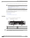
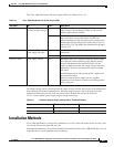
The DC power input connector euro-style terminal block will accept three wires: one positive polarity,
one negative polarity, and one earth ground wire. There is provisions on the front panel to wire tie and
strain relief the DC input wiring. The connection order shall be negative (–), positive (+), GND. The DC
power supply is secured into the system chassis with two captive screws mounted on the faceplate.
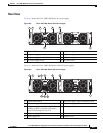
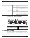
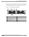
Figure 6-6 shows the DC Power Supply for the Cisco ASR1002 Router.
Figure 6-6 DC Power Supply for the Cisco ASR 1002 Router
1 Chassis ESD socket 6 DC power supply captive installation screw
2 DC power supply slot 0 label 7 DC power supply slot 1 label
3 DC power supply switch Standby/On (I)
(standby symbol is a broken circle with a
vertical line through the top of it)
8 Earth ground lead
4 DC power supply LEDs 9 Positive lead
5 Fan 10 Negative lead
280289
OUTPUTINPUT
FAIL
OK OK
FAN
-48V/-60V 16A
This unit might have more than
one power supply connection.
All connections must be removed
to de-energize the unit.
OUTPUTINPUT
FAIL
OK OK
FAN
-48V/-60V 16A
This unit might have more than
one power supply connection.
All connections must be removed
to de-energize the unit.
9 810
4 5 63
0
1
7
1
2