


5-4
Cisco ASR 1000 Series Aggregation Services Routers Hardware Installation and Initial Configuration Guide
OL-13208-03
Chapter 5 Cisco ASR 1004 Router Overview and Installation
Cisco ASR 1004 Router Description
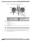
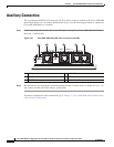
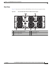
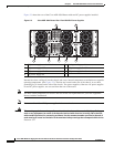
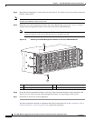
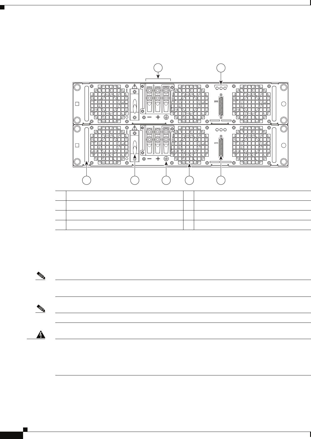
Figure 5-3 shows the rear of the Cisco ASR 1004 Router with two DC power supplies installed.
Figure 5-3 Cisco ASR 1004 Router Rear View With DC Power Supplies
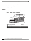
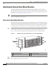
Internal fans draw cooling air into the chassis and across internal components to maintain an acceptable
operating temperature. (See
Figure 5-2.) The fans are located at the rear of the chassis. A two-hole
grounding lug is located on the side of the chassis. Two power supplies, either two AC power supplies
or two DC power supplies, are accessed from the rear of the router.
Note You have already unpacked your chassis and read all the site requirements for your new equipment.
Proceed with the installation.
Note Do not combine AC and DC power supplies in the same chassis.
Warning
This warning symbol means danger. You are in a situation that could cause bodily injury. Before you
work on any equipment, be aware of the hazards involved with electrical circuitry and be familiar
with standard practices for preventing accidents. Use the statement number provided at the end of
each warning to locate its translation in the translated safety warnings that accompanied this device.
Statement 1071
1 DC power supply terminal block 5 Earth grounding symbol
2 DC power supply LEDs 6 DC power supply On/Off switch
3 DC power supply DB-25 alarm connector 7 DC power supply handle
4 DC power supply fan
280185
OUTPUT INPUT
FAIL
OK OK
FAN
60V
1A MAX
OUTPUT INPUT
FAIL
OK OK
FAN
60V
1A MAX
1
2
345
67