


8-46
Cisco ASR 1000 Series Aggregation Services Routers Hardware Installation and Initial Configuration Guide
OL-13208-03
Chapter 8 Replacing Cisco ASR 1000 Series Routers Field-Replaceable Units
Removing and Replacing a Cisco ASR 1002 Router Power Supply
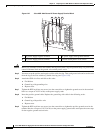
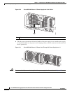
Step 5 Unscrew all of the power supply captive screws.
Note Two power supplies must be installed in the chassis at all times to ensure sufficient cooling. The
system fans are inside the power supply units and must spin for cooling. Because all the system
fans can be powered by one power supply, the second power supply unit does not have to be
powered on, but it must be installed.
Caution If you remove a power supply, the system can run for a maximum of five minutes before the system shuts
down. The fans and power elements are independent within the power supply. Therefore, it is not
required that the replacement power supply be energized within five minutes. The only requirement is
that the power supply be installed in the chassis, which energizes the fans and maintains proper system
cooling.
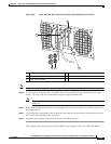
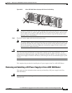
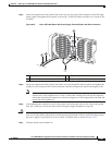
Step 6 Grasping the power supply handles, pull the power supply from the chassis.
Step 7 Replace the DC power supply within five minutes.
This completes the procedure of removing a DC power supply from the Cisco ASR 1002 Router.
Replacing the DC Power Supply in Cisco ASR 1002 Router
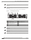
The DC power supply input connector is a euro-style terminal block. Features are provide for strain
relieving the input wires from the terminal block on the front panel. The ground wire must contain a loop
when secured to prevent any strain on the wires. The connection order is negative (–), positive (+), and
GND. The recommended branch circuit breaker for the Cisco ASR 1002 Router DC power supply is
30Amp. Use an AWG #10 gauge wire on the 30Amp circuit.
This section describes how to connect the DC power supply in a Cisco ASR 1002 Router.
Note The color coding of the DC-input power supply leads depends on the color coding of the DC power
source at your site. Typically, green or green/yellow is used for ground. Make certain the lead color
coding you choose for the DC-input power supply matches lead color coding used at the DC power
source.
Warning
When you install the unit, the ground connection must always be made first and disconnected last.
Statement 1046
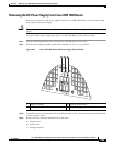
Step 1 At the rear of the router, check that the power Standby switch is in the Standby position.
Step 2 Ensure that the positive and negative leads are disconnected from the site power source and the source
circuit breaker is turned off.
Step 3 Using a wire stripper, strip approximately 0.55 inch (14 mm) from the negative, positive, and ground
lead.