


6-31
Cisco ASR 1000 Series Aggregation Services Routers Hardware Installation and Initial Configuration Guide
OL-13208-03
Chapter 6 Cisco ASR 1002 Router Overview and Installation
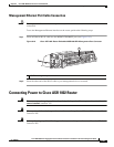
Connecting Power to Cisco ASR 1002 Router
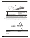
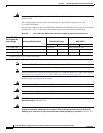
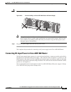
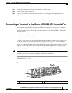
Caution Do not run the AC power cord through the power supply handles as shown in Figure 6-23.
Figure 6-23 Incorrect Cabling on Cisco ASR 1002 Router AC Power Supply
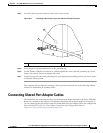
Note Using a tie wrap for the AC power cable is optional and not necessary. However, if you do attach
the AC power cable to a power supply tab and then you remove the AC power cable for some
reason, check for any damage to the cable after you cut the tie wrap off. If the power cord is
damaged, replace it immediately.
Step 4 Plug the AC power supply cable into the AC power source.
This completes the procedure for connecting an AC power supply in the Cisco ASR 1002 Router.
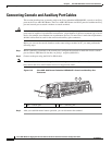
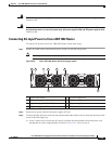
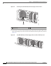
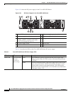
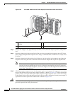
Connecting DC-Input Power to Cisco ASR 1002 Router
The DC power supply input connector is a euro-style terminal block. A means to provide strain relief to
the input wires is provided on the power supply. The connection order is negative (–), positive (+), and
GND; but this is the order from left to right that the terminals appear on the power supply, not the order
in which the leads should connected during installation. The order the leads should be attached is GND,
positive (+), and negative (-).
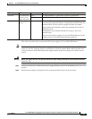
The recommended branch circuit breaker for the Cisco ASR 1002 Router DC power supply is 30Amp.
Use a AWG #10 wire gauge on the 30Amp circuit.
280378
O
UT
PU
T
IN
P
U
T
F
AI
L
O
K
OK
FA
N
Th
i
s un
i
t mi
ght
have mo
r
e
than
on
e
po
w
e
r
s
upp
l
y
con
n
e
c
t
io
n
.
A
ll
co
n
n
ec
t
i
on
s
must
b
e remove
d
to
d
e-e
ne
r
g
i
z
e th
e
u
ni
t
.
O
UT
PU
T
IN
P
U
T
F
AI
L
O
K
OK
FA
N
Th
i
s un
i
t m
ight
have m
o
r
e
than
on
e
po
w
e
r
s
upp
l
y
c
on
n
e
c
t
io
n
.
Al
l
con
n
ec
t
i
on
s
m
u
st
b
e
rem
o
ve
d
to de-en
e
r
gi
z
e
the u
ni
t
.