


4-19
Cisco ASR 1000 Series Aggregation Services Routers Hardware Installation and Initial Configuration Guide
OL-13208-03
Chapter 4 Cisco ASR 1006 Router Overview and Installation
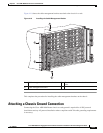
Attaching a Chassis Ground Connection
Recommended Tools and Supplies
The following tools, equipment, and supplies necessary to connect the system ground to the chassis:
• Phillips screwdriver
• Dual-lug chassis ground component
• Grounding wire
Use the following procedure to attach the grounding lug to the chassis ground connector on your chassis:
Step 1 Use the wire stripper to strip one end of the AWG #6 wire approximately 0.75 inches (19.05 mm).
Step 2 Insert the AWG #6 wire into the wire receptacle on the grounding lug.
Step 3 Use the crimping tool to carefully crimp the wire receptacle around the wire; this step is required to
ensure a proper mechanical connection.
Step 4 Attach the grounding lug with the wire so that the grounding wire does not overlap the power supply.
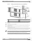
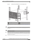
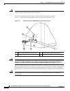
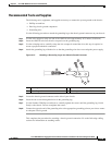
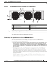
Figure 4-12 Attaching a Grounding Lug to the Chassis Ground Connector
Step 5 Locate the chassis ground connector on the side of your chassis.
Step 6 Insert the two screws through the holes in the grounding lug.
Step 7 Use the Number 2 Phillips screwdriver to carefully tighten the screws until the grounding lug is held
firmly to the chassis. Do not overtighten the screws.
Step 8 Connect the opposite end of the grounding wire to the appropriate grounding point at your site to ensure
an adequate chassis ground.
This completes the procedure for attaching a chassis ground connection. Go to the following cabling
sections for information on attaching cables.
1 Chassis ground lead wire 3 Ground screws
2 Grounding stud 4 Chassis ground connector holes
280186
4
1
2
3