


6-6
Cisco ASR 1000 Series Aggregation Services Routers Hardware Installation and Initial Configuration Guide
OL-13208-03
Chapter 6 Cisco ASR 1002 Router Overview and Installation
Cisco ASR 1002 Router Description
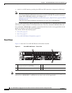
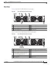
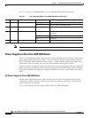
Table 6-1 lists the Cisco ASR1000-ESP5 or Cisco ASR1000-ESP10 LEDs and behaviors.
Note The Cisco ASR 1000-ESP5 can only be used in the Cisco ASR 1002 Router.
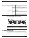
Power Supplies in the Cisco ASR 1002 Router
The Cisco ASR 1002 Router power supply module consists of either an AC or DC input in a closed frame
power supply with two DC voltage outputs: +12V and 3.3V. The AC power supply operates between
85VAC to 264VAC and DC operates between –40.5 to –72VDC. The DC and AC power supply shall
current share on the 12V output and is used in a dual (redundant) hot pluggable system.
The power supplies are installed into the rear of the chassis and are hot pluggable. The Cisco ASR 1002
Router supports up to 588W input power from an infrastructure standpoint (cooling capacity, midplane
and power distribution) but initial power supply development limit is up to 470W output (AC and DC
Input).
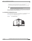
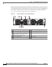
AC Power Supply for Cisco ASR 1002 Router
The AC power supply input inlet is an IEC connector with AC switch and the current rating on the
connector and switch is 10 Amps. The AC power supply is secured into the chassis with two captive
screws mounted on the faceplate.
Table 6-2 describes the AC power supply LEDs on the Cisco ASR 1002 Router.
Table 6-1 Cisco ASR 1000-ESP5 or Cisco ASR1000-ESP10 LED Activity
No LED Label LED Color In the Power Up State -Behavior Description
1 PWR Power Solid green All power supplies are within operational limits.
Off Off, the router is in standby mode.
2ACTV Active Green
The embedded services processor is green when
active.
3 STAT STATUS Green Code has successfully downloaded and is
operational.
Yellow BOOT ROM has successfully loaded.
Red Not booted.
4 STBY Standby None Will always be off.