


4-20
Cisco ASR 1000 Series Aggregation Services Routers Hardware Installation and Initial Configuration Guide
OL-13208-03
Chapter 4 Cisco ASR 1006 Router Overview and Installation
Connecting Shared Port Adapter Cables
Connecting Shared Port Adapter Cables
The instructions for connecting the cables for the shared port adapter installed in the Cisco ASR 1006
Router are contained in the respective configuration documents for each port adapter. For example, if
you are connecting the optical fiber cables for the PA-POS-OC3 port adapter, refer to the configuration
note PA-POS-OC3 Packet OC-3 Port Adapter Installation and Configuration Guide at
http://www.cisco.com/univercd/cc/td/doc/product/core
Shared port adapter documents are also available on the Cisco Documentation DVD.
Connecting Console and Auxiliary Port Cables
The Cisco ASR 1006 Router has a DCE-mode console port for connecting a console terminal and a
DTE-mode auxiliary port for connecting a modem or other DCE device (such as another router) to your
chassis.
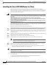
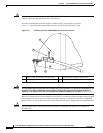
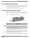
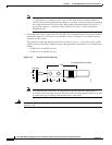
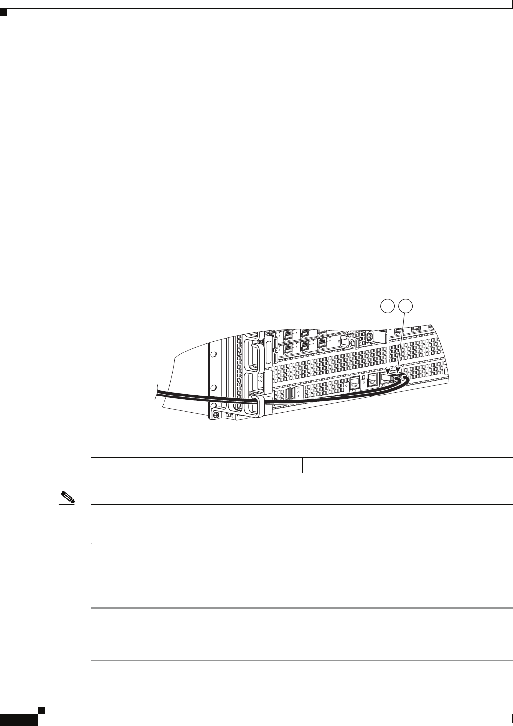
Figure 4-13 shows the CON and AUX ports on the Cisco ASR 1000 Series RP1 route processor
card.
Figure 4-13 Cisco ASR 1000 Series RP1—CON and AUX Ports
Note Both the console and the auxiliary ports are asynchronous serial ports; any devices connected to these
ports must be capable of asynchronous transmission. (Asynchronous is the most common type of serial
device; for example, most modems are asynchronous devices.)
The Cisco ASR 1006 Router uses RJ-45 ports for both the auxiliary port and the console port.
For console and auxiliary port pinouts for the RJ-45 connector, see Appendix A, “Cisco ASR 1006
Router Specifications.” Both ports are configured as asynchronous serial ports.
Step 1 Before connecting a terminal to the console port, configure the terminal to match the chassis console
port as follows: 9600 baud, 8 data bits, no parity, 1 stop bits (9600 8N1).
Step 2 After you establish normal router operation, you can disconnect the terminal.
MI
N
A
C
O
MA
J
ST
B
Y
A
CTV
S
TA
T
A
S
R
1
00
0-
R
P
1
P
WR
C
RI
T
0
S
P
A
-
4
X
O
C
3
-
P
O
S
0
1
2
3
A
A/
L
C/
A
A
/L
C/
A
A
/L
S
P
A
-
4
XO
C
3
-
P
O
S
S
TATUS
0
1
2
3
C/
A
A
/L
C/
A
A
/
L
C/A
A/
L
C/A
A
/L
SP
A
-
4
XO
C
3
-
P
O
S
S
T
AT
US
0
1
2
3
C/
A
A
/L
C/
A
A/
L
C/A
A
/
L
C/
A
A
/L
B
I
T
S
C
O
N
A
UX
C
A
R
R
IER
LIN
K
M
G
M
T
E
T
H
E
R
N
E
T
D
I
S
K
H
D
U
S
B
D
F
0
1
280181
1 2
1 CON connector 2 AUX connector