


8-47
Cisco ASR 1000 Series Aggregation Services Routers Hardware Installation and Initial Configuration Guide
OL-13208-03
Chapter 8 Replacing Cisco ASR 1000 Series Routers Field-Replaceable Units
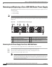
Removing and Replacing a Cisco ASR 1002 Router Power Supply
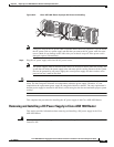
Step 4 Insert the stripped end of the ground lead all the way into the ground lead receptacle on the DC-input
power supply, and tighten the receptacle screw using a 3.5mm flat-blade screwdriver to a torque of 0.5
to 0.6Nm.
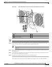
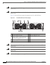
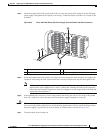
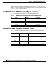
Figure 8-35 Cisco ASR 1002 Router DC Power Supply Terminal Block Lead Wire Connection
Step 5 Insert the stripped end of the positive lead all the way into the positive lead receptacle and tighten the
receptacle screw using the same 3.5mm flat-blade screwdriver. Repeat this step for the negative lead.
Note Make sure the entire stripped end of each lead is inserted all the way into its receptacle. If any
exposed wire at the stripped end of a lead is visible after inserting the lead into its receptacle,
remove the lead from the receptacle, use the wire stripper to cut the stripped end of the lead, and
repeat Step 3 through Step 5.
Step 6 After tightening the receptacle screw for the ground, and leaving the extra service loop in the ground
lead, use a cable tie to secure the three leads to the power supply faceplate tie-wrap tab.
Caution When securing the ground, positive, and negative DC-input leads to the power supply faceplate, leave
extra service loop in the ground lead to ensure that the ground lead is the last lead to disconnect from
the power supply if a great deal of strain is placed on all three leads as shown in Figure 8-35.
Step 7 Turn the branch source breaker on.
1 Earth ground lead wire with service loop 3 Positive lead wire
2 Negative lead wire 4 DC power supply Standby switch
OUTPUTINPUT
FAIL
O
KOK
FAN
-4
8
V
/-60
V
1
6A
Thi
s un
it m
ig
h
t
h
ave mor
e
tha
n
one power supply connection.
All con
nections m
u
st
be rem
o
v
ed
to
d
e-
e
nergize the unit.
3
1
2
280290
4