


5-20
Cisco ASR 1000 Series Aggregation Services Routers Hardware Installation and Initial Configuration Guide
OL-13208-03
Chapter 5 Cisco ASR 1004 Router Overview and Installation
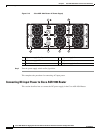
Connecting Shared Port Adapter Cables
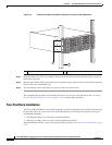
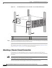
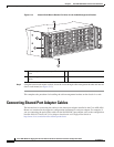
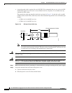
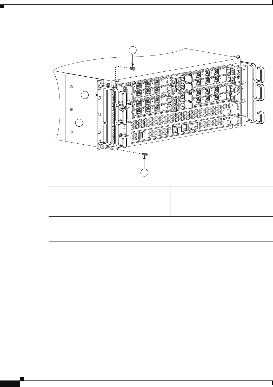
Figure 5-13 Chassis Rack-Mount Bracket Ear Holes for the Cable-Management Bracket
Step 3 Using the bottom rack-mount ear hole, insert the screw through cable-management bracket and into the
chassis rack-mount (see
Figure 5-13).
This completes the procedure for installing the cable-management brackets on the chassis in a rack.
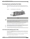
Connecting Shared Port Adapter Cables
The instructions for connecting the cables for the shared port adapter installed in the Cisco ASR 1004
Router are contained in the respective configuration documents for each port adapter. For example, if
you are connecting the optical fiber cables for the PA-POS-OC3 port adapter, refer to the configuration
note PA-POS-OC3 Packet OC-3 Port Adapter Installation and Configuration Guide at
http://www.cisco.com/univercd/cc/td/doc/product/core
1 Cable-management bracket top and bottom
screw
3 Chassis rack-mount bracket
2 Cable-management bracket and U feature
device
280176
SP
A
-
4
X
O
C
3
-
P
O
S
S
TATUS
0
1
2
3
C/
A
A
/L
C
/
A
A/L
C/
A
A
/L
C/
A
A
/L
SP
A
-
4
X
O
C
3
-
P
O
S
S
T
AT
US
0
1
2
3
C/
A
A/L
C
/
A
A/L
C
/A
A
/L
C
/
A
A
/L
S
P
A
-
4
X
O
C
3
-
P
O
S
S
TATUS
0
1
2
3
C/
A
A/L
C/A
A/
L
C/A
A
/
L
C/
A
A
/L
S
P
A
-
4
X
O
C
3
-
P
O
S
S
T
A
T
US
0
1
2
3
C/
A
A/L
C/A
A/
L
C/A
A
/L
C/
A
A
/L
S
P
A
-
4
XO
C
3
-
P
O
S
S
TATUS
0
1
2
3
C/A
A/L
C/
A
A/
L
C/
A
A
/
L
C/A
A
/L
SP
A
-
4
XO
C
3
-
P
O
S
S
T
AT
US
0
1
2
3
C/A
A
/
L
C
/
A
A
/
L
C/
A
A/L
C/
A
A
/L
S
P
A
-
4
XO
C
3
-
P
O
S
S
TATUS
0
1
2
3
C/
A
A
/L
C
/
A
A
/
L
C/
A
A/
L
C/A
A
/L
SP
A
-
4
XO
C
3
-
P
O
S
S
T
AT
US
0
1
2
3
C/
A
A
/L
C/
A
A/
L
C/
A
A
/
L
C/
A
A
/L
1
1
MI
N
AC
O
MA
J
ST
B
Y
A
CT
V
S
TAT
A
S
R
1
0
0
0-
R
P
1
P
WR
C
RI
T
B
I
T
S
C
O
N
A
U
X
C
A
R
R
I
E
R
L
I
N
K
M
G
M
T
E
T
H
E
RN
E
T
D
I
S
K
H
D
U
S
B
D
F
0
1
3
2