


7-2
Cisco ASR 1000 Series Aggregation Services Routers Installation and Initial Configuration Guide
OL-13208-03
Chapter 7 Cisco ASR 1000 Series Routers Power Up and Initial Configuration
Verifying Power Supply Operation
• You have selected passwords for access control.
• Captive installation screws are tight on all removable components.
• The console terminal is turned on.
• You have determined the IP addresses for the Ethernet and serial interfaces.
• Empty card slots or card bays are filled with card blanks. This ensures proper air flow through the
chassis and electromagnetic compatibility (EMC).
You are now ready to start your router.
Verifying Power Supply Operation
Follow this procedure to verify power supply is operating correctly.
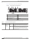
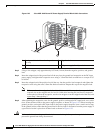
Step 1 Check that the power supply LEDs are:
• INPUT OK is green
• FAN OK is green
• OUTPUT FAILED is not illuminated
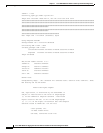
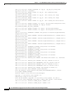
Step 2 To ensure that the power supply state is OK, type the show platform command. This output sample is
from a Cisco ASR1006 router. The other Cisco ASR1000 routers display similar type of output.
MCP_SCAL_R1#sho plat
Chassis type: ASR1006
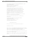
The following output displays:
MCP_SCAL_R1#
If the LEDs indicate a power problem or the power supply state is ps,fail, then contact a customer service
representatives for assistance or additional instructions.
Slot Type State Insert Time
1 ASR1000-SIP10 ok 00:03:19
1/1 SPA-8X1GE-V2 ok 00:02:23
2 ASR1000-SIP10 ok 00:03:19
2/0 SPA-1X10GE-L-V2 ok 00:02:22
2/1 SPA-8X1GE-V2 ok 00:02:17
R0 ASR1000-RP1 ok,active 00:03:19
F0 ASR1000-ESP20 ok,active 00:03:19
P0 ASR1006-PWR-AC ok 00:02:50
P1 ASR1006-PWR-AC ps, fail 00:02:50
Slot CPLD Version Firmware
Version
1 07091401 12.2(33r)XN2
2 07091401 12.2(33r)XN2
R0 08060301 12.2(0:0)
F0 08041102 12.2(33r)XN2