


5-28
Cisco ASR 1000 Series Aggregation Services Routers Hardware Installation and Initial Configuration Guide
OL-13208-03
Chapter 5 Cisco ASR 1004 Router Overview and Installation
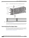
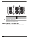
Connecting Power to Cisco ASR 1004 Router
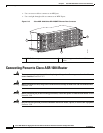
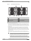
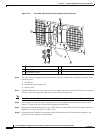
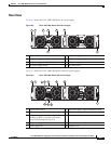
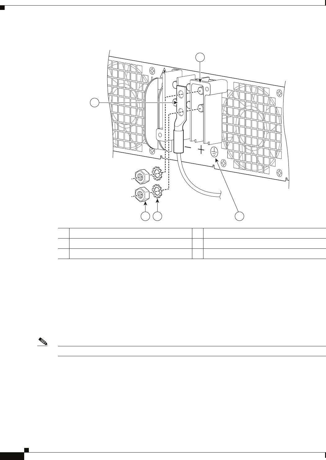
Figure 5-20 Cisco ASR 1004 Router DC Power Supply Cable Connection
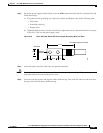
Step 6 For easier cable-management, insert the negative cable first. Replace the ground lug with cable in the
following order:
a. Flat Washer
b. Ground lug with negative wire
c. Kepnut screw
Step 7 Tighten the Kepnut screw (use the screwdriver to tighten the screw in the terminal block to a torque of
8 in-lbs / 4 per.) and repeat the same steps for the positive stud and wire.
Note Secure the wires coming in from the terminal block so that they cannot be disturbed by casual contact.
Step 8 Use tie wraps to secure the wires, so that the wires are not pulled from the terminal block by casual
contact. Ti-wrap studs are located below the supply terminal block.
Step 9 Replace the terminal block plastic cover, which slides over the terminal block; then tighten the screws
(tighten the screw to a torque of 5 in-lbs / 1 per.).
Step 10 Remove the tape from the circuit-breaker switch handle and move the circuit-breaker handle to the
on
position, if you taped the circuit breaker.
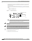
1 Power supply stud and wire 4 Flat washer
2 Ground lug nut 5 Kepnut screw
3 Earth ground symbol
280187
2
5 4 3
1