


B-15
Cisco ASR 1000 Series Aggregation Services Routers Hardware Installation and Initial Configuration Guide
OL-13208-03
Appendix B Troubleshooting Initial Startup Problems
General Troubleshooting Tips
Troubleshooting Using a Subsystem Approach
To solve a system problem, try to isolate the problem to a specific subsystem. Compare current router
behavior with expected router behavior. Because a startup issue is usually attributable to one component,
it is most efficient to examine each subsystem, rather than trying to troubleshoot each router component.
For troubleshooting purposes in this chapter, the router consists of the following subsystems:
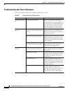
• Power subsystem—Includes the following components:
–
AC-input or DC-input power supplies, also called power entry modules (PEMs). The Cisco ASR
1000 Series Router is shipped with fully-redundant PEMs installed in the chassis.
• Processor subsystem—The Cisco ASR1000 RP, ESPs, and SIPs all have onboard processors. The
RP downloads software to each board in the system over the Ethernet Out of Band Channel (EOBC).
There is a status LED on each board (RP1, ESP, SIP) that indicates the progress of loading software.
The LED is red if ROMMON does not boot. If the board has booted ROMMON successfully, the
LED is yellow. If operation software (IOS) has downloaded successfully, the LED is green.
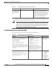
• Cooling subsystem—Consists of three fans in each of the Cisco ASR 1006 Router and Cisco ASR
1004 Router power supplies and two fans in each of the Cisco ASR 1002 Router power supplies.
The fans draw in air from each of the chassis and PEMs in a front to back direction.
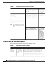
Normal Router Startup Sequence
You can generally determine when and where the power supply failed during the startup sequence by
checking the status LEDs on the power supply modules.
In a normal router startup sequence, the following sequence of events and conditions occur:
1. The fan in each PEM receives power and begins drawing air through the power supply. The power
supply PWR OK indicator is on and reflects power supply status.
2. As the power on and boot process progresses for the Cisco ASR 1000 Series RP1, ASR1000 ESPs,
and each installed SIP, the status of each card is indicated by LEDs.