


8-38
Cisco ASR 1000 Series Aggregation Services Routers Hardware Installation and Initial Configuration Guide
OL-13208-03
Chapter 8 Replacing Cisco ASR 1000 Series Routers Field-Replaceable Units
Removing and Replacing a DC Power Supply in Cisco ASR 1004 Router
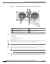
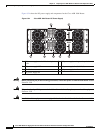
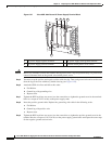
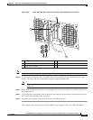
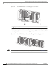
Figure 8-27 Cisco ASR 1004 Router DC Power Supply Terminal Block
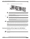
Caution Before you continue to install the terminal block ground wires, stop and perform Step 5 to prevent any
contact with metal lead on the ground wire and the plastic cover.
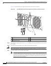
Step 5 You must wrap the positive and negative cables with sleeving. Take each ground wire and cover the area
from the lug to the wire with heavy shrink sleeving (see
Figure 8-20).
Step 6 Attach the GND wire first and follow this order:
a. Flat Washer
b. Ground lug with grounding wire
c. Kepnut screw
Step 7 Tighten the KEP-style hex nut screws (use the screwdriver to tighten the ground screw in the terminal
block to a torque of 18-22 in-lbs) on the power supply studs
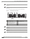
Step 8 Insert the positive ground cable. Replace the ground lug with cable in the following order:
a. Flat Washer
b. Ground lug with positive wire
c. Kepnut screw
Step 9 Tighten the KEP-style hex nut screws (use the screwdriver to tighten the positive ground screw in the
terminal block to a torque of 18-22 in-lbs) on the power supply ground studs and repeat the same steps
for the negative ground stud and wire.
1 DC power supply negative terminal 3 DC power supply earth ground terminal
2 DC power supply positive terminal 4 Terminal block plastic cover screws
4
1 2 3 4
280188