


2-8
Cisco ASR 1000 Series Aggregation Services Routers Hardware Installation and Initial Configuration Guide
OL-13208-03
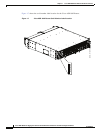
Chapter 2 Cisco ASR 1000 Series Routers Components
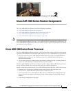
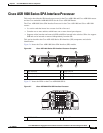
Cisco ASR 1000 Series Route Processor
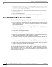
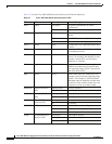
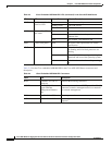
Table 2-4 lists the Cisco embedded ASR1000-RP1in the Cisco ASR 1002 Router connectors and
description.
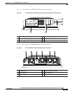
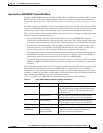
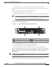
LINK 10/100 /1000 RJ-45
Interface LED
Green Link with no activity.
Flashing Green Link with activity.
Off No link.
4 LEDs Built-in SPA SFP
port status
Off Port is not enabled.
Amber Port enabled but there is a problem with the
Ethernet link.
Green Port enabled, valid Ethernet link
PWR Carrier card power Green All carrier card requirements are within
specification.
STAT Carrier card status Green Only when the SPA drivers have started and
are running and all critical processes are
running
Yellow When ROMMON is running and during the
download and boot of the operating system
Red A fault is detected or the card is powering
up.
Table 2-3 Cisco Embedded ASR1000-RP1 LEDs (continued) in the Cisco ASR 1002 Router
LED Label LED Color —State Behavior Description
Table 2-4 Cisco Embedded ASR1000-RP1 Connectors
Label Type Description
BITS Standard E1/T1 RJ-45
connector
Indicates BITS timing references.
MGMT
One RJ-45 jack for
copper Ethernet
Management Ethernet
Port
The route processor has an ENET port with a RJ-45
connector to attach a management device or network
for network management.
CON One RJ-45 for CON Console port used to connect to a terminal.
AUX One RJ-45 for AUX Auxiliary port used for remote management
purposes.