


4-28
Cisco ASR 1000 Series Aggregation Services Routers Hardware Installation and Initial Configuration Guide
OL-13208-03
Chapter 4 Cisco ASR 1006 Router Overview and Installation
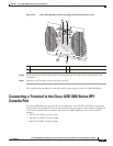
Connecting a Terminal to the Cisco ASR 1000 Series RP1 Console Port
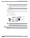
A crossover cable reverses pin connections from one end to the other. In other words, it connects pin 1
(at one end) to pin 8 (at the other end), pin 2 to pin 7, pin
3 to pin 6, and so on. You can identify a
crossover cable by comparing the two modular ends of the cable. Hold the cable ends in your hand,
side-by-side, with the tabs at the back. Ensure that the wire connected to the outside (left) pin of the left
plug (pin 1) is the same color as the wire connected to the outside (right) pin of the right plug (pin 8).
Use the following procedure to connect a video terminal to the console port on a route processor.
Note Each Cisco ASR 1000 Series Route Processor 1 must have a console port connection (typically to a
terminal server) if you are running a redundant configuration in the chassis.
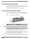
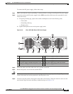
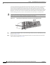
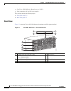
Figure 4-19 Console Port and Auxiliary Port Connection on the ASR 1000 Series RP1
Step 1 Connect one end of the RJ-45 cables to the serial RJ-45 port (CON) on the Cisco ASR 1000 Series Route
Processor 1 (
Figure 4-19).
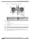
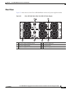
Step 2 Run the cable up and through the cable-management bracket and connect the other end of the RJ-45
cable to the RJ-45 adapter (
Figure 4-20).
280094
B
IT
S
C
O
NAU
X
CARR
IE
R
L
INK
M
G
M
T
E
T
H
E
R
N
ET
B
IT
SC
O
N
AU
X
CARR
IE
R
L
INK
M
G
M
T
E
T
H
E
R
N
E
T
1 2