


5-27
Cisco ASR 1000 Series Aggregation Services Routers Hardware Installation and Initial Configuration Guide
OL-13208-03
Chapter 5 Cisco ASR 1004 Router Overview and Installation
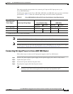
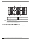
Connecting Power to Cisco ASR 1004 Router
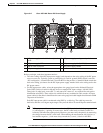
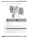
Step 3 On the DC power supply terminal block, locate the GND connection which must be connected first and
follow these steps:
a. Using the two-hole grounding lug, replace the washers and Kepnut screw in the following order.
–
Flat washer
–
Grounding cable lug
–
Kepnut screw
b. Tighten the Kepnut screws (use the screwdriver to tighten the screw in the terminal block to a torque
of 8 in-lbs / 2 per.) on the power supply studs.
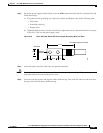
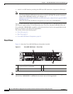
Figure 5-19 Cisco ASR 1004 Router DC Power Supply Grounding Wire and Stud
Step 4 Attach the other end of the cable to the site ground connection.
Caution Before you continue to install the terminal block wires, stop and perform Step 5. To prevent any contact
with metal lead on the wire and the plastic cover.
Step 5 You must wrap the positive and negative cables with sleeving. Take each wire and cover the area from
the lug to the wire with heavy shrink sleeving.
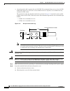
Crimp area
25527
2.24
0.48
0.08
0.25 0.370.63
End View
Ø 0.267
2 holes
All measurements in inches