


6-21
Cisco ASR 1000 Series Aggregation Services Routers Hardware Installation and Initial Configuration Guide
OL-13208-03
Chapter 6 Cisco ASR 1002 Router Overview and Installation
Attaching the Cable-Management Bracket
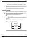
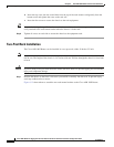
Step 6 Use a level to verify that the tops of the two brackets are level, or use a measuring tape to verify that both
brackets are the same distance from the top of the rack rails.
This completes the procedure for installing the chassis in the rack. Proceed to the “Attaching the
Cable-Management Bracket” section on page 6-21 to continue the installation.
Attaching the Cable-Management Bracket
The cable-management brackets mount to each rack-mount bracket on the chassis to provide
cable-management to both sides of the chassis (parallel with card orientation). These brackets are screw
mounted to the rack-mount brackets to allow easy installation and removal of cables.
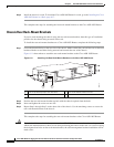
The cable-management brackets for the Cisco ASR 1002 Router contain one independent
cable-management “U” type features with four screws and provides cable dressing of each card module
slot.
Note Make certain that the cable-management bracket “U” type feature is facing upwards when you attach it
to the chassis.
Follow these steps to attach the cable-management brackets to both sides of the Cisco ASR 1002 Router
in the rack:
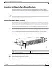
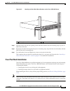
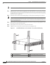
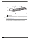
Step 1 Align the cable-management bracket to the rack-mount bracket on one side of the Cisco ASR 1002
Router. The cable-management bracket aligns to the top hole of the chassis rack-mount bracket.
Step 2 Using a Phillips screwdriver, insert the screw through cable-management bracket and into the chassis
rack-mount and tighten the screw.
Note Use the package of screws that came with your chassis containing four screws.
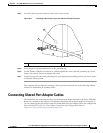
Figure 6-14 shows where to attach the front rack-mount brackets to the Cisco ASR 1002 Router in a rack.