


1-5
Cisco ASR 1000 Series Aggregaion Services Routers Hardware Installation and Initial Configuration Guide
OL-13208-03
Chapter 1 Cisco ASR 1000 Series Routers Hardware Overview
Functional Overview
Chassis Slot and Logical Interface Numbering
The Cisco ASR 1000 Series Routers have a slot numbering system located on both sides of the card
module location. The chassis slots are physically numbered from zero starting at the bottom of the
chassis. This section describes the slot numbering for the Cisco ASR 1000 Series Routers:
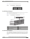
• Cisco ASR 1006 Router Slot Numbering, page 1-5
• Cisco ASR 1004 Router Slot Numbering, page 1-7
• Cisco ASR 1002 Router Slot Numbering, page 1-7
Cisco ASR 1000 Series SPA Interface Processor (SIP) subslots begin their numbering with “0” and have
a horizontal orientation. The SIP subslot numbering is indicated by a small numeric label beside the
subslot on the faceplate. Some commands allow you to display information about the SPA itself, such as
show idprom module and show hw-module subslot. These commands require you to specify both the
physical location of the SIP and SPA in the format, Slot/Subslot, where:
• Slot—Specifies the chassis slot number in the Cisco ASR 1000 Series Routers where the SIP is
installed.
• Subslot—Specifies a subslot of the SIP where the SPA is installed.
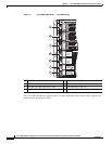
Cisco ASR 1006 Router Slot Numbering
The Cisco ASR 1006 Router is designed with each slot numbered as shown in Figure 1-1.