


4-26
Cisco ASR 1000 Series Aggregation Services Routers Hardware Installation and Initial Configuration Guide
OL-13208-03
Chapter 4 Cisco ASR 1006 Router Overview and Installation
Connecting Power to Cisco ASR 1006 Router
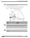
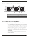
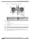
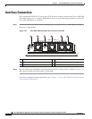
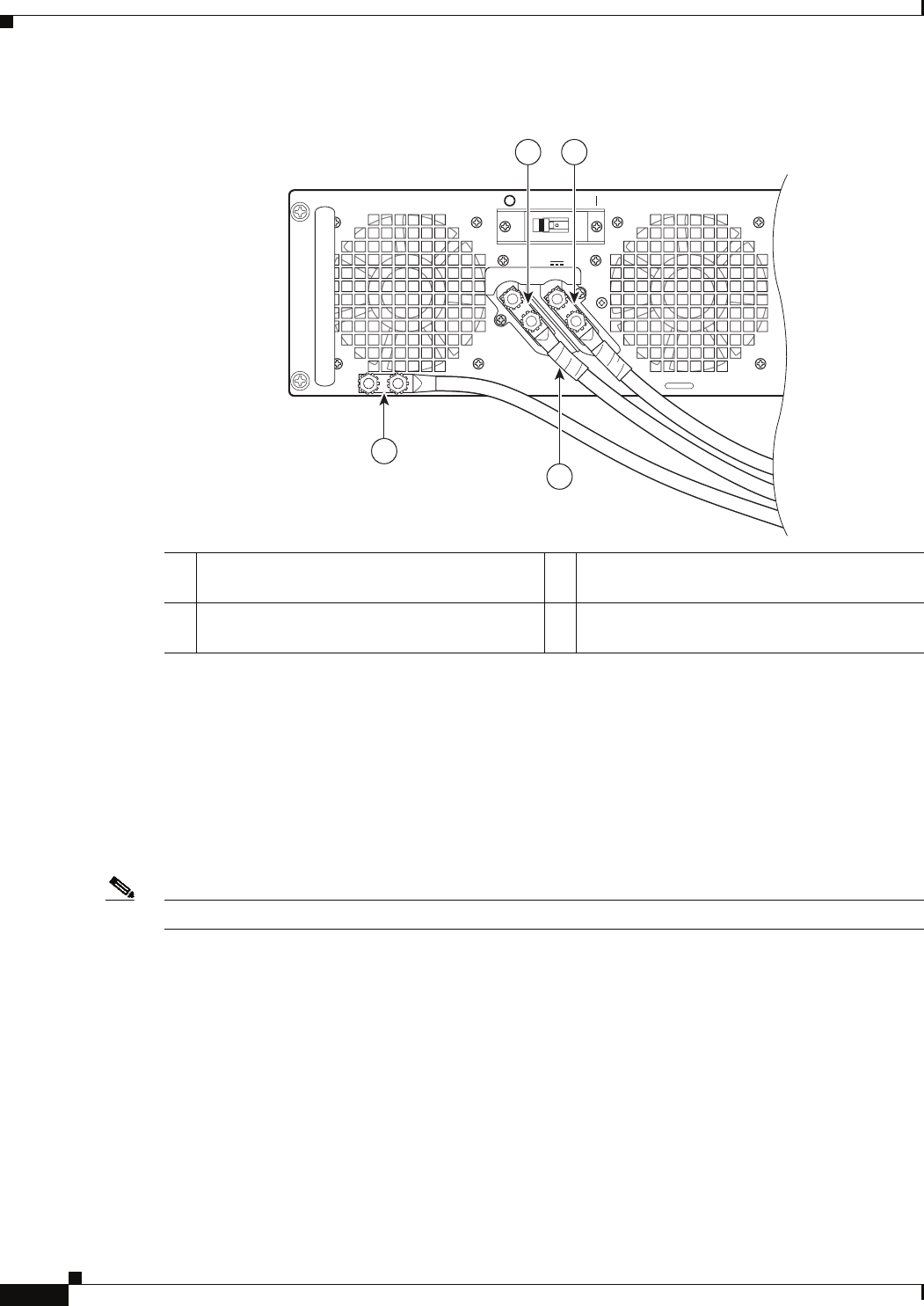
Figure 4-17 DC Power Supply Terminal Block Ground Cable Lugs
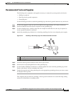
Step 6 For easier cable-management, insert the negative lead cable first. Replace the ground lug with cable in
the following order:
a. Flat Washer
b. Ground lug with negative wire
c. Kepnut screw
Step 7 Tighten the Kepnut screw to recommended torque of 18 in-lbs minimum to 22 in-lbs maximum for the
positive stud and wire.
Note Secure the wires coming in from the terminal block so that they cannot be disturbed by casual contact.
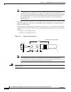
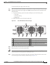
Step 8 Use tie wraps to secure the wires, so that the wires are not pulled from the terminal block by casual
contact. Ti-wrap studs are located below the power supply terminal block (see
Figure 4-18).
Step 9 Replace the terminal block plastic cover and tighten the screw. The plastic cover is slotted and keyed to
fit correctly over the terminal block.
1 Negative lug and wire with sleeving wrapped
around the wire and end of lug
3 Location of sleeving wrapped around the wire
and end of the grounding stud
2 Positive lug and wire with sleeving wrapped
around the wire and end of lug
4 Earth ground lug and wire
This unit might have more than one power supply connection. All connections must be removed to de-energ
OFF
-48/-60V 40A
280024
1 2
4
3