


2-7
Cisco ASR 1000 Series Aggregation Services Routers Hardware Installation and Initial Configuration Guide
OL-13208-03
Chapter 2 Cisco ASR 1000 Series Routers Components
Cisco ASR 1000 Series Route Processor
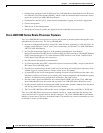
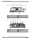
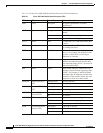
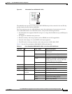
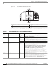
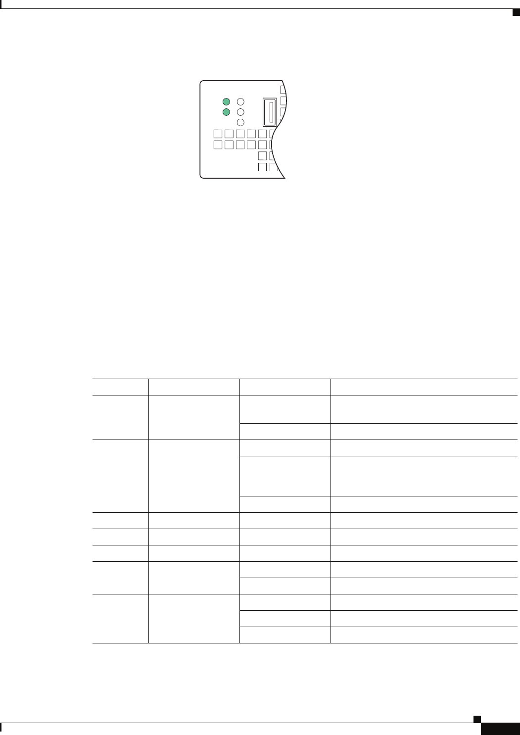
Figure 2-3 Embedded Cisco ASR1000-RP1 LEDs
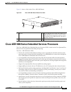
The embedded route processors for the Cisco ASR 1002 Router provides connection for one SPA bay
and the circuitry for the a built-in 4xGE SPA.
The Cisco route processor for ASR 1002 Router meets the requirements of route processors for the
Cisco
ASR 1006 and the Cisco ASR 1004 routers; except for the following deviations:
• No SATA hard drive supported. Bulk file storage is on a large fixed eUSB device (up to 8GB (bytes)
supported).
• No support for redundant route processors.
• Hardware memory and storage options (such as DRAM) are not field upgradeable.
• Network clock changes. No second BITS clock input supported.
• The LED order is from top to bottom on the route processor is MIN, MAJ, CRIT.
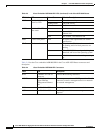
Table 2-3 lists the Cisco embedded ASR1000-RP1 LEDs and behaviors.
ASR 1002
pwr
stat
min
maj
crit
250603
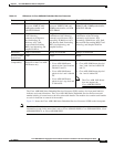
Table 2-3 Cisco Embedded ASR1000-RP1 LEDs in the Cisco ASR 1002 Router
LED Label LED Color —State Behavior Description
PWR Power Solid green All power requirements are within
specification
Off Off, the router is in standby mode.
STAT System status Solid green Cisco IOS has successfully booted.
Yellow ROMMON is running or when the Process
Manager declares that a critical ASR 1000
Series RP1 process is not running
Red System failure or powering up.
MIN Minor Amber Minor alarm indicator.
MAJ Major Red Major alarm indicator.
CRIT Critical Red Critical alarm indicator.
BOOT eUSB0 FLASH
(BootDisk
Flashing Green Activity indicator.
Off No activity.
CARRIER Off Out of service or not configured.
Green In frame and working properly.
Amber Fault or loop condition.