


6-14
Cisco ASR 1000 Series Aggregation Services Routers Hardware Installation and Initial Configuration Guide
OL-13208-03
Chapter 6 Cisco ASR 1002 Router Overview and Installation
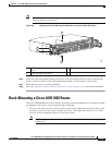
Rack-Mounting a Cisco ASR 1002 Router
• Four post, 19-inch equipment rack. Inner clearance (the width between the inner sides of the two
posts or rails) must be at least 19 inches (48.26
cm). The height of the chassis is 3.47 inches (8.8
cm). Airflow through the chassis is from front to back.
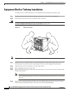
Note When handling the chassis, always follow proper lifting practices, see Chassis-Lifting Guidelines, page
3-20.
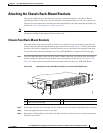
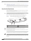
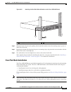
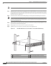
The Cisco ASR 1002 Router can be installed with both front or rear rack-mount brackets.
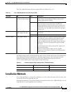
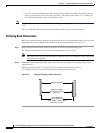
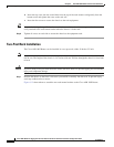
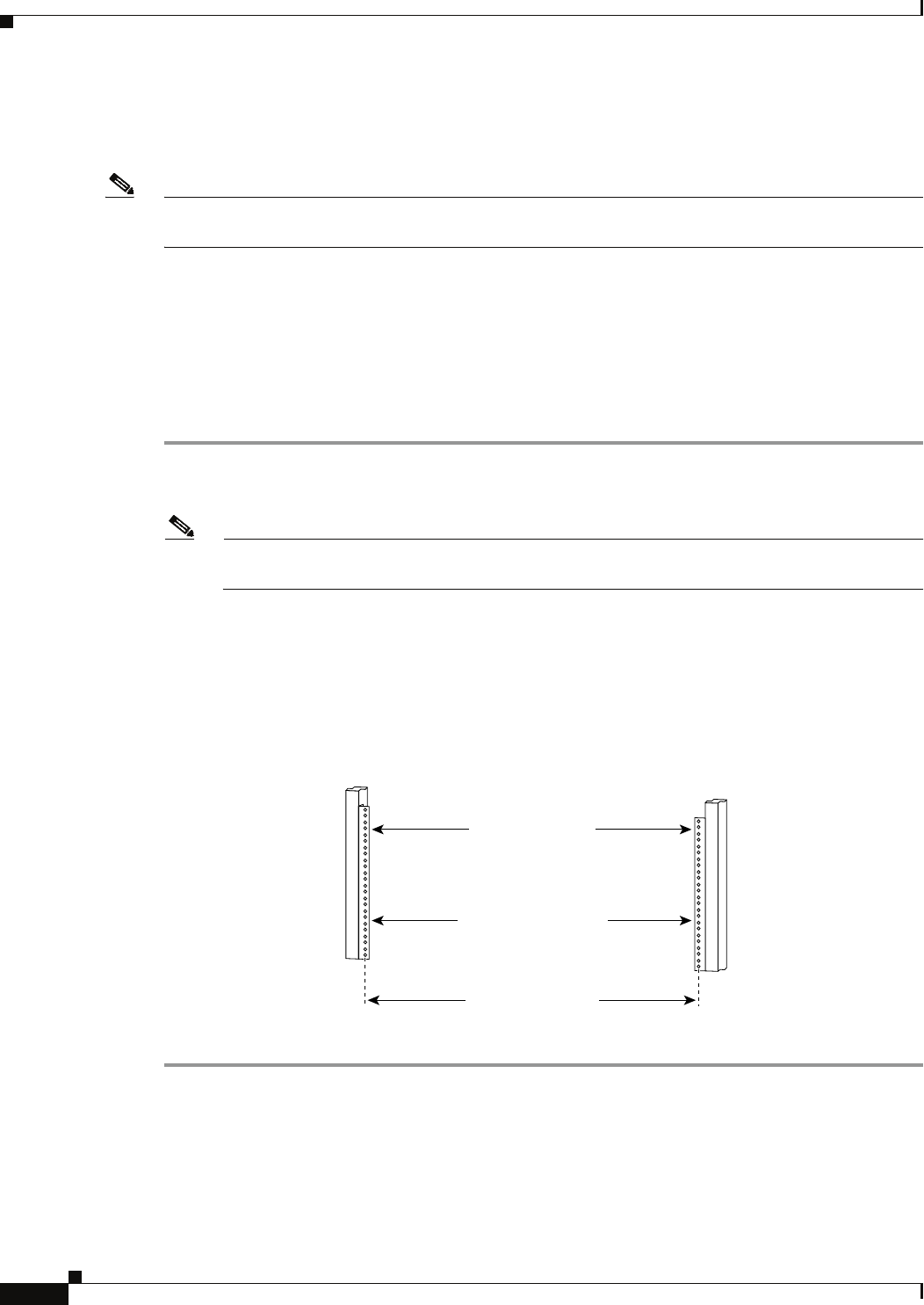
Verifying Rack Dimensions
Before you install the chassis, measure the space between the vertical mounting flanges (rails) on your
equipment rack to verify that the rack conforms to the measurements shown in
Figure 6-9.
Step 1 Mark and measure the distance between two holes on the left and right mounting rails.
The distance should measure 18.31 inches ± 0.06 inches (46.5 cm ± 0.15 cm).
Note Measure for pairs of holes near the bottom, middle and top of the equipment rack to ensure that
the rack posts are parallel.
Step 2 Measure the space between the inner edges of the left front and right front mounting flanges on the
equipment rack.
The space must be at least 17.7 inches (45 cm) to accommodate the chassis which is
17.25
inches (43.8 cm) wide and fits between the mounting posts on the rack.
Figure 6-9 Verifying Equipment Rack Dimensions
Minimum usable
aperture 17.7 inches
(45.0 cm)
Hole centerline
to hole centerline
18.31 inches ± 0.06 inches
(46.5 cm ± 0.15 cm)
Mounting flanges
28014