


8-29
Cisco ASR 1000 Series Aggregation Services Routers Hardware Installation and Initial Configuration Guide
OL-13208-03
Chapter 8 Replacing Cisco ASR 1000 Series Routers Field-Replaceable Units
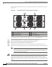
Removing and Replacing a Cisco ASR 1006 Router Power Supply
Step 10 Replace the DC power supply within five minutes.
This completes the procedure of removing a DC power supply from the Cisco ASR 1006 Router.
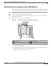
Replacing the DC Power Supply in Cisco ASR 1006 Router
Note The color coding of the DC-input power supply leads depends on the color coding of the DC power
source at your site. Typically, green or green/yellow is used for ground (GND), black is used for -48V
on negative (–) terminal and red is used for RTN on the positive (+) terminal. Make certain the lead color
coding you choose for the DC-input power supply matches lead color coding used at the DC power
source.
Warning
When you install the unit, the ground connection must always be made first and disconnected last.
Statement 1046
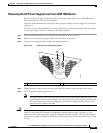
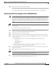
To install the DC power supply, follow these steps:
Step 1 Grasp the DC power supply by the two handles and carefully slide it into the chassis. Make sure you
align the rear connector to the backplane until it is fully seated.
Step 2 Tighten the captive screws on the power supply.
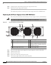
Step 3 Make certain that the chassis ground is connected before you begin installing the DC power supply.
Step 4 Locate the ground stud on the DC power supply for the GND connection which must be installed first
and follow these steps:
a. Using the grounding lug, replace the washers and Kepnut screw in the following order.
–
Flat washer
–
Grounding cable lug
–
Kepnut screw
b. Tighten the Kepnut screws (use the screwdriver to tighten the ground screw to a torque of
20+/–2
in-lbs / 2 per.) on the power supply ground studs.
Step 5 Attach the other end of the ground cable to the site ground associated to the DC power supply system
that you are working on.
Step 6 Remove the plastic cover from the terminal block if it is still on.
Caution Before you continue to install the terminal block ground wires, stop and perform Step 7. This is to
prevent any contact between the metal power lugs and plastic cover.
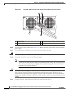
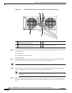
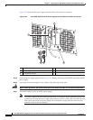
Step 7 You must wrap the positive and negative power cables with sleeving. Take each wire and cover the area
from the lug to the wire with heavy shrink sleeving (see
Figure 8-21.)