


CHAPTER
5-1
Cisco ASR 1000 Series Aggregation Services Routers Hardware Installation and Initial Configuration Guide
OL-13208-03
5
Cisco ASR 1004 Router Overview and Installation
This chapter describes the Cisco ASR 1004 Router and the procedures for installing the Cisco ASR 1004
Router on an equipment shelf or tabletop or in equipment racks. It also describes how to connect
interface and power cables.
This chapter contains the following sections:
• Cisco ASR 1004 Router Description, page 5-1
• General Rack Installation Guidelines, page 5-5
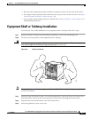
• Guidelines for an Equipment Shelf or Tabletop Installation, page 5-6
• Equipment Shelf or Tabletop Installation, page 5-7
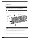
• Rack-Mounting a Cisco ASR 1004 Router, page 5-9
• Attaching a Chassis Ground Connection, page 5-16
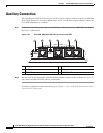
• Connecting Power to Cisco ASR 1004 Router, page 5-22
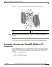
• Connecting a Terminal to the Cisco ASR Series 1000 RP1 Console Port, page 5-29
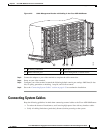
• Connecting Network Management and Signal System Cables, page 5-30
Warning
This warning symbol means danger. You are in a situation that could cause bodily injury. Before you
work on any equipment, be aware of the hazards involved with electrical circuitry and be familiar
with standard practices for preventing accidents. Use the statement number provided at the end of
each warning to locate its translation in the translated safety warnings that accompanied this device.
Statement 1071
Warning
Before you install, operate, or service the system, read the Regulatory Compliance and Safety
Information for Cisco ASR 1000 Series Aggregation Services Routers publication. This document
provides important safety information you should know before working with the system.
Statement 200
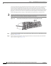
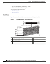
Cisco ASR 1004 Router Description
The Cisco ASR 1004 Router system consists of the following system level components:
• Two Cisco ASR 1000 Series SPA Interface Processor (SIP)
• One Cisco ASR 1000 Series Embedded Services Processor (Cisco ASR 1000-ESP10 or Cisco
ASR
1000-ESP20)