


8-84 Removal and Installation
HP DesignJet CP Series Printers
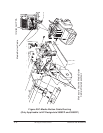
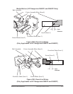
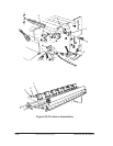
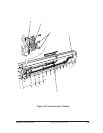
Pincharm Assemblies, Pincharm Shaft and
Pincharm Sensor
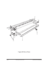
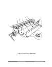
Refer to figure 28 ' page 8-86
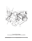
Removal of the pincharm sensor
WARNING
Switch off the printer and remove the power cord.
1. Remove the following:
1. Right Hand Cover ' page 8-21.
2. Service Station Assembly ' page 8-26
2. Remove the two T-10 screws (item 1) securing the pincharm sensor to the
right hand side chassis.
3. Remove the pincharm sensor cable from the cable clamp (item 2) secured
to the left hand side chassis.
4. Disconnect the pincharm sensor cable from the electronics module in
position J8 PINCH.
Removal of the pincharm assemblies and the pincharm shaft.
1. Remove the following:
1. Window and Top Cover ' page 8-15.
2. Left Hand Cover ' page 8-18.
3. Right Hand Cover ' page 8-21.
4. Service Station Assembly ' page 8-26.
5. Overdrive assembly and Drive roller ' page 8-69.
2. To remove the pincharm shaft (item 6), loosen the T-9 screw (item 3) at
the right end of the pincharm shaft. Be careful not to loosen the screw
too much as you may loose the nut (item 5)
3. Remove the top half of the elevator assembly by releasing it from two
retaining clips at the back and lifting up and to the left.
4. Pull out the cam journal (item 4) from the hole in the right hand side
chassis
5. Remove the pincharm shaft from the left side of the printer by pulling it
out.
6. To remove any of the pincharm assemblies (item 7) pull out from the
chassis.