


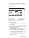
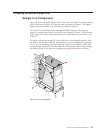
Threading the Buffer/Flipper Unit
Straight Line Configuration
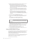
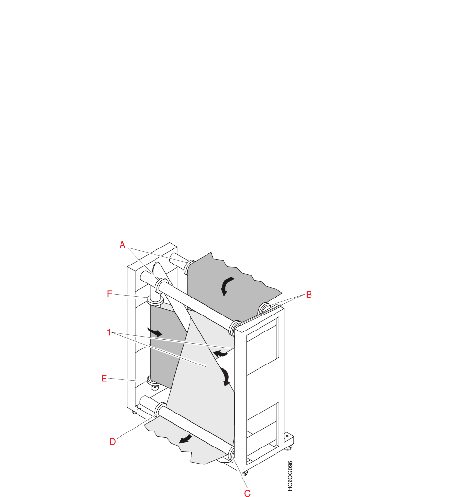
Figure 32 shows the Buffer/Flipper Unit viewed from the front. The darker shaded
side of the forms in Figure 32 is the side that is printed on Printer 1. The lighter
shaded side of the forms is the side that is printed on Printer 2.
Use Figure 32 to thread the forms through the Buffer/Flipper Unit using the
arrows as a guide from Printer 1 at the top of the figure to Printer 2 at the bottom
of the figure. The result is that the forms are inverted 180° between Printer 1 and
Printer 2.
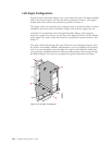
The guide collars (A) through (F) on the roller bars were adjusted properly when
the system was initially installed. Adjustments by you are probably not necessary,
even if you are threading a form through the system with a different width than
you previously threaded. When the forms are under tension and moving through
the Buffer/Flipper Unit, they run up against the guide collars that are shown.
Figure 32. Inline Configuration
Chapter 6. Operator Responsibilities 167