


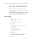
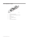

This power-driven roller assembly is on the floor in the forms input area of
the second printer of the system; the continuous forms are threaded through
it. It assists in feeding forms from the Buffer/Flipper Unit under the printer
into the tractor feed area of the printer.
Duplex Printing Applications
The following configurations support Duplex (double-sided) printing.
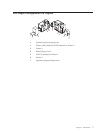
Duplex printing is achieved by arranging both a Model ED1 and a Model ED2 in
series, separated by a Buffer/Flipper Unit. The first printer in the paper path prints
one side of a form. The forms then exit the printer through a Buffer/Flipper Unit,
which inverts them before threading them through the second printer. The second
printer in the paper path prints the other side of the form.
This publication calls the first printer Printer 1 and the second printer Printer 2.
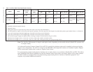
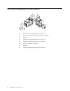
Allowable printer system configurations are inline (see “Inline Configuration for
Duplex” on page 6), or a left 90° angle (see “Left Angle Configuration for Duplex”
on page 7). Only a Buffer/Flipper Unit may be between Printer 1 and Printer 2,
but no preprocessing or postprocessing devices.
The forms path can be:
v From the forms input area of Printer 1 through to the output stacker of Printer 2
v From the forms input area to a postprocessing device at the output of Printer 2
v From a preprocessing device ahead of Printer 1 through to a postprocessing
device at the output of Printer 2.
Both printers in the configuration attach to a host system through the AFCCU. The
AFCCU controls both printers simultaneously and is physically attached to Printer
2 in the configuration.
4 InfoPrint 3000 Operator’s Guide