


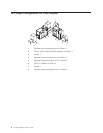
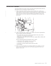

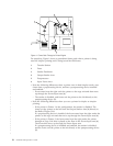
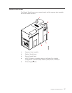
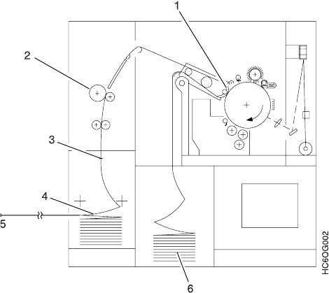
For simplicity, Figure 1 shows a generalized forms path when a printer is being
used for simplex printing and is using boxed fan-fold forms.
1 Transfer Station
2 Fuser
3 Stacker Pendulum
4 Output Stacker Area
5 Postprocessor
6 Input Forms Area
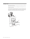
v Note the following differences when a printer runs in dual simplex mode, uses
forms from a preprocessing device, and has a postprocessing device installed
and enabled:
– Forms enter from the right under the printer to the urge unit and then move
up through the Forms Input area (6).
– The stacker is disabled, and forms exit the printer to the left directly to the
postprocessing device (5).
v Note the following differences when you use a printer for duplex or simplex
printing:
– If the printer is Printer 1 in the configuration, the stacker is disabled. The
forms exit the printer to the left from the Output Stacker Area (4) directly to
the Buffer/Flipper Unit.
If a preprocessing device is installed, the forms enter from the right under the
printer to the urge unit and then move up through the Forms Input area (6).
– If the printer is Printer 2, the forms enter from the right under the printer
through an Urge Unit that is placed on the floor in the Forms Input area (6).
The forms then move up through the Forms Input area.
If a postprocessing device is installed and enabled, the stacker is disabled,
and the forms exit the printer to the left directly to the postprocessing device
(5).
Figure 1. Forms Path Through a Printer Engine
16 InfoPrint 3000 Operator’s Guide
|
|
|
|
|
|
|
|
|
|
|
|
|
|
|
|
|
|
|
|
|