


Avaya P550R, P580, P880, and P882 Multiservice Switch User Guide, v5.3.1 9-39
Configuring IP Routing
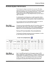
Identify the Ports
The chassis is organized by slots, fabric ports, PRE/F-chip’s, and
physical ports. The number of F-Chips and physical ports vary with
the module type. This information is useful in spreading the
workload evenly among resources, and identifying possible choke
points:
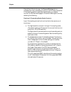
■ Every Fabric port can manage up to 4 F-Chips
■ Slot 1 has 1 Fabric port only
■ Slots 2-7 (P580) and Slots 2-17 (P882) have 2 Fabric ports
per slot
■ The Supervisor has 1 F-chip (FORE)
■ The 8-port GigE has 8 F-Chips (4 per Fabric port)
■ The 4-port GigE has 4 F-Chips (2 per Fabric port)
■ The 24-port Ethernet modules (copper or fiber) have 2 F-
Chips (1 per Fabric port). Physical Ports 1-12 correspond with
F-Chip 1, and Physical Ports 13-24 correspond with F-Chip 2.
■ The 48-port Ethernet has 4 F-Chips (2 per Fabric port) with
the following Physical Port to F-Chip correspondence: ports
1-12: F-Chip 1, ports 13-24: F-Chip 2, ports 25-36: F-Chip 3,
ports 37-48: F-Chip 4.
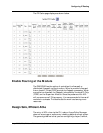
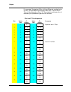
Fabric ports are numbered regardless of whether other slots are
empty or full.
For switch code version 5.3.1, F-Chips numbers are associated with
their respective Fabric ports. To locate the Fabric port and F-Chip for
Physical Port you need to know the media type and slot.