


173
3-23 ERPS
The chapter describes Ethernet Ring Protection Switching (ERPS). ITU-T under G.8032
recommended this to provide sub-50ms protection and recovery switching for Ethernet traffic
in a ring topology, and at the same time ensuring that there are no loops formed at the
Ethernet layer. Ethernet Ring Protection Switch instances are configured here.
Web Interface
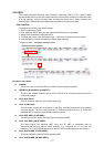
To configure the ERPS in the Web interface:
1. Click Configuration, ERPS.
2. Click “Add new ERPS” then you can create new ERPS entry on the switch.
3. Assign each parameter to add new ERPS.
4. To cancel the setting, click the Reset button. It will revert to previously saved values
5. Click Refresh and switch will update the ERPS table manually.
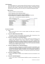
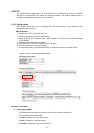
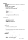
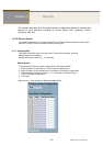
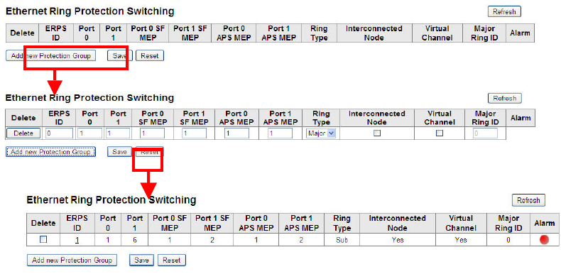
Figure 3-24.1: The ERPS Configuration.
Parameter description:
Delete:
This box is used to mark an ERPS for deletion in the next Save operation.
ERPS ID (Protection group ID) :
The ID of the created Protection group. Click on the ID of an Protection group to enter the
configuration page. .
Port 0 (E Port):
This will create an East port of the switch in the ring.
Port 1 (W Port):
This will create a West port of the switch in the Ring. As interconnected sub-ring will have
only one ring port, "W port" is configured as "0" for interconnected sub-ring. "0" in this field
indicates that no west port is associated with this instance.
Port 0 SF MEP (E SF MEP):
The field you need to assign the East Signal Fail reporting MEP.
Port 1 SF MEP (W SF MEP):
The West Signal Fail reporting MEP. Only one SF MEP is associated with an
interconnected sub-ring without virtual channel; it is configured as "0" for such ring
instances. "0" in this field indicates that no west SF MEP is associated with this instance.
Port 0 APS MEP (E APS MEP):
This field assigns the East APS PDU handling MEP.
Port 1 APS MEP (W APS MEP):