6
Configuring an F_Port Extension over an Ethernet WAN
6-7
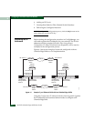
Configuring a 2x2 Ethernet Wide Area Network
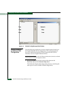
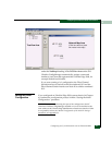
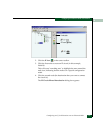
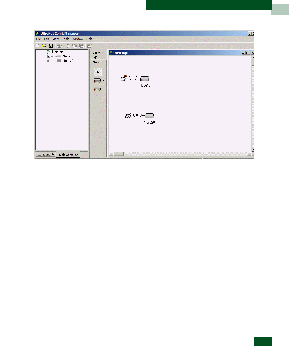
The node icons and their corresponding names are also displayed
under the NetMap1 heading in the TreeView Area on the left.
UltraNet ConfigManager automatically assigns a name and
number to each icon that represents the UltraNet Edge 3000, for
example Node10 and Node20.
If you were creating a 1x1 configuration, the Fibre Channel
Switch interface on Node10 would be numbered 10-2 and the
Fibre Channel Switch interface on Node 20 would be numbered
20-2.
Setting the Initial
Configuration
If you configured an UltraNet Edge 3000 custom chassis (in Chapter
4), continue the configuration process with the “Setting the Initial
Configuration” procedure.
NOTE: When you are performing this part of the configuration, the PC
which has UltraNet ConfigManager installed on it, must be attached to the
same subnet as the UltraNet Edge 3000 Ethernet maintenance interface. If this
is not possible, refer to the “Manual Configuration of the Initial IP Settings”
procedure, see Appendix H.
Network Map Area
(Click here twice to place
two nodes in the map)
TreeView Area


