6
Configuring an F_Port Extension over an Ethernet WAN
6-21
Configuring a 2x2 Ethernet Wide Area Network
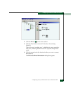
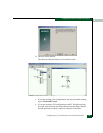
To view details about this circuit and its provider interfaces,
double-click on the circuit connection in the network diagram.
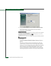
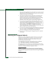
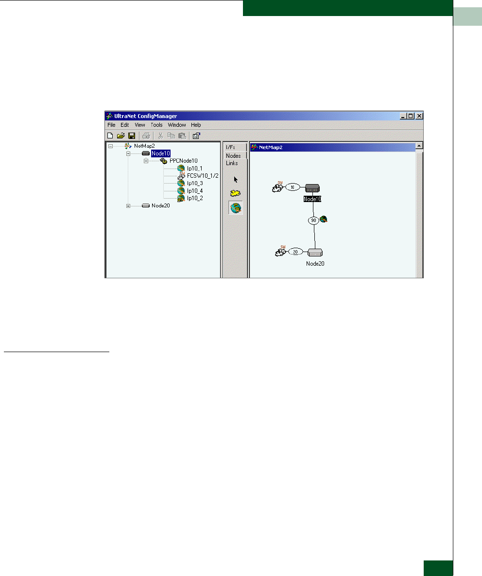
Once you have completed the above steps for a 2x2 Gigabit
Ethernet WAN configuration, your network map should look like
the following example:
19. Repeat steps in the “Adding an IP Circuit” section to create the
second IP circuit.
20. Continue the configuration process by following the “Creating
Data Paths for Fibre Channel Switch Interfaces” section.
Creating Data Paths
for Fibre Channel
Switch Interfaces
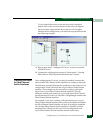
After configuring the IP circuit, you need to establish a connection
between the Fibre Channel Switch interfaces by creating a data path.
The following example illustrates the creation of a data path for a 2x2
configuration, where each node has a 2-port Fibre Channel Switch
interface. This example can also be used for creating a data path
between two 1-port Fibre Channel Switch interfaces. The only
difference in data path creation for 1-port and 2-port Fibre Channel
Switch interfaces is in the way UltraNet ConfigManager numbers the
Fibre Channel Switch interfaces.
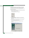
For example, if you were creating a data path between two 1-port
Fibre Channel Switch interfaces and you had a Node10 and Node20,
the Fibre Channel Switch interface on Node 10 would be numbered
10-2 and the Fibre Channel Switch interface on Node20 would be
numbered 20-2. Whereas in the case of a 2x2 configuration with
2-port Fibre Channel Switch interfaces and the same nodes


