9
Configuring Tape Device Extension
9-3
Network Configuration Examples
Example of
Bi-directional
Configuration with
Zoning
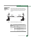
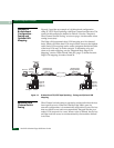
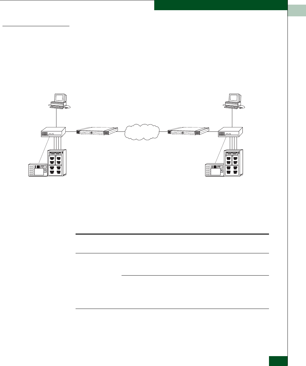
Figure 8-2 provides an example of a bi-directional configuration
using FC/SCSI Tape Pipelining. Table
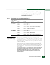
8-1 defines the Fibre Channel
switch zones required for this example. No static Edge LUN mapping
is required for this configuration. See the “Required Fibre Channel
Switch Zoning” section on page
-4 to determine when zoning is
necessary.
Figure 9-2 Bi-directional FC/SCSI Tape Pipelining - with Zoning
Sb043
Server A Server B
UltraNet Edge
Storage Router
Node 10
UltraNet Edge
Storage Router
Node 20
Media
Change 2r
Tape
Drives
Tape A1
Tape A2
Tape B1
Media
Changer 1
Tape B2
Tape
Drives
Fibre
Channel
Switch 2
Fibre
Channel
Switch 1
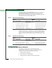
Table 9-1 Fibre Channel Switch Zoning Definitions for Figure 8-2
Fibre Channel
Switch
Zone Device
FC Switch 1
Zone 1 Server A, Edge 10
Zone 2 Edge 10, Tape B2, Media Changer 1
FC Switch 2
Zone 1 Server B, Edge 20
Zone 2 Server B, Tape B1, Media Changer 2
Zone 3 Edge 20, Tape A1, Tape A2, Media Changer 2


