9
Configuring Tape Device Extension
9-11
Configuring Tape Device Extension
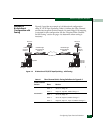
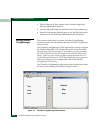
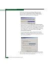
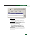
Figure 8-4 is an example of the main window in ConfigManager
(UCM).
Adding Nodes for
an Ethernet WAN
Configuration
Use the following procedures to create a sample network map for a
1x1 10/100 Ethernet WAN configuration. This configuration will
have two nodes that extend one Fibre Channel device extension
interface over one 10/100 Ethernet WAN.
The procedure that follows is for a 1x1 configuration.
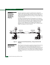
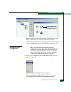
1. Select the Nodes tab located on the toolbar between the TreeView
Area and the Network Map Area (see Figure
8-4 on page -11).
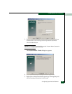
The Nodes tab displays three drop-down menus. Each contains
the node types for the available Edge series.
2. Click the arrow next to the UltraNet Edge 3000 Series drop-down
menu and select the Edge3000 (1x1 - 10/100 Mbps Ethernet) node
type.
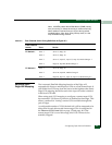
NOTE: This example is for a 1x1 Ethernet 10/100 WAN configuration. If you
are configuring any other model, choose the appropriate node icon shown in
the table above to create your map.
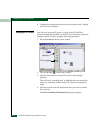
The cursor will turn into crosshairs once you move the cursor
over the map area. The cursor must be crosshairs to complete the
current operation.
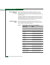
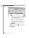
3. Click in the Network Map Area to create an instance of the
UltraNet Edge 3000 node.
Adding a Fibre Channel Interface
Links tab
Interface tab
Nodes tab
UltraNet Edge 1000 Series
UltraNet Edge 3000 Series


