9
9-4
McDATA UltraNet Edge 3000 User Guide
Network Configuration Examples
Example of
Bi-directional
Configuration -
Zoning and
Optional LUN
Mapping
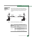
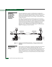
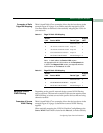
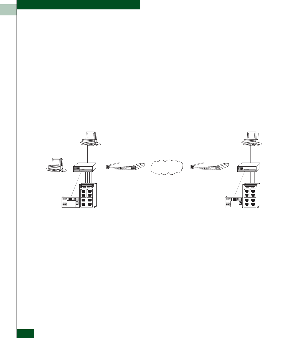
Figure 8-3 provides an example of a bi-directional configuration
using FC/SCSI Tape Pipelining with Fibre Channel switch zones. The
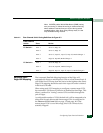
zones for this example are defined in Table
8-2. See the “Required
Fibre Channel Switch Zoning” section on page
-4 to determine when
zoning is necessary.
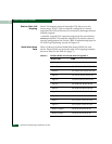
The Edge will do automatic host LUN mapping on a first learned
basis, which will fill the host LUN map from the lowest to the highest
order. Static LUN mapping can be used to designate the desired order
of the host LUN map, as in this example. To determine why and
when to do static mapping, see the “Required Static Edge LUN
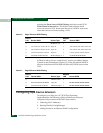
Mapping” section. Table
8-4 and Table 8-5 (page -7) define the static
Edge LUN mapping for nodes 10 and 20.
Figure 9-3 Bi-directional FC/SCSI Tape Pipelining - Zoning and Optional LUN
Mapping
Required Fibre
Channel Switch
Zoning
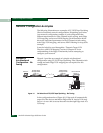
Fibre Channel switch zoning is required to isolate individual devices
from specific servers. When an UltraNet Edge 3000 is part of a
network configuration, it is automatically mapped to its peer. Devices
that are visible to one node are automatically mapped into the peer
node’s LUN map and vice versa. When a zone is defined, the devices
an Edge node has access to are determined by the members defined
in its zone.
Sb044
Server C Server B
UltraNet Edge
Storage Router
Node 10
UltraNet Edge
Storage Router
Node 20
Media
Change 2r
Tape
Drives
Tape A1
Tape A2
Tape B1
Media
Changer 1
Server A
Tape C4
Tape B2
Tape C1
Tape C2
Tape C3
Tape
Drives
Fibre
Channel
Switch 2
Fibre
Channel
Switch 1


