


4
Performing Port Diagnostics
4-31
Repair Information
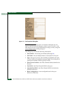
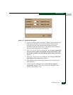
9. Verify beaconing is enabled, then click Next. The message Press
START Test to begin diagnostics appears, and the Next button
changes to a Start Test button.
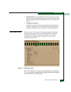
10. Click Start Test. The test begins and:
—The Start Test button changes to a Stop Test button
— The message Port xx: Test running appears, where xx is the
port number.
— A red progress bar (indicating percent completion) travels
from left to right across the Completion Status field.
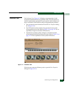
As a port is tested, the amber LED flashes (beacons) and the green
LED extinguishes (indicating the port is blocked).
NOTE: Click Stop Test at any time to abort the loopback test.
11. When the test completes, test results appear (for each port tested)
as Port xx: Passed! or Port xx: Failed! in the message area of the
dialog box. If a port fails the test, the amber LED for the port
remains illuminated.
12. When finished, click Cancel to close the Port Diagnostics dialog box
and return to the Hardware View. Beaconing is disabled for the
port.
13. Reset each tested port.
External Loopback
Test
To perform an external loopback test for a single port:
1. Notify the customer that a disruptive external loopback test will
be performed on a port and the fiber-optic cable or cables will be
disconnected. Ensure the customer’s system administrator
quiesces Fibre Channel frame traffic through the port and sets
attached devices offline.
NOTE: At the start of the loopback test, the port can be online, offline,
blocked, or unblocked.
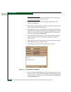
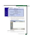
2. At the EFC Server, open the EFC Manager application. The
Product View displays.
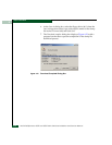
3. Select the icon representing the switch for which the loopback test
is to be performed. The Hardware View for the selected switch
displays.