


2
2-24
McDATA® Sphereon 3032 and 3232 Fabric Switches Installation and Service Manual
Installation Tasks
b. Connect the remaining end of the Ethernet cable to the
corporate intranet as directed by the customer’s network
administrator.
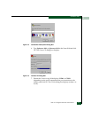
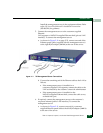
7. As shown in Figure 2-11, connect the 20-foot phone cord to the
left RJ-11 adapter (LINE) at the rear of the server and to a facility
telephone connection.
8. As shown in Figure 2-11, connect the AC power cord to the server
and to a facility power source or rack power strip that provides
single-phase, 90 to 264 VAC current.
9. When the power cord is connected, the management server
powers on and performs power-on self-tests (POSTs). During
POSTs:
a. The green liquid crystal display (LCD) panel illuminates.
b. The green hard disk drive (HDD) LED blinks momentarily,
and processor speed and random-access memory information
display momentarily at the LCD panel.
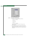
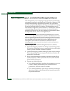
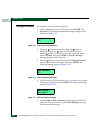
c. After a few seconds, the LCD panel displays the following
message pertaining to boot sequence selection (Figure 2-12):
Figure 2-12 LCD Panel During Boot Sequence
d. Ignore the message. After ten seconds, the server performs the
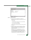
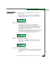
boot sequence from the basic input/output system (BIOS).
During the boot sequence, the server performs additional
POSTs and displays the following information at the LCD
panel:
•Host name.
• System date and time.
• LAN 1 and LAN 2 IP addresses.
• Fan 1, fan 2, fan 3, and fan 4 rotational speed.
• Central processing unit (CPU) temperature.
• Hard disk capacity.
• Virtual and physical memory capacity.
Boot from LAN?
Press <Enter>