


2
Task 2: Unpack, Inspect, and Install the Ethernet Hub (Optional)
2-9
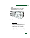
Installation Tasks
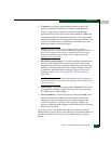
2. Position the first hub on a table or desktop as directed by the
customer.
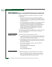
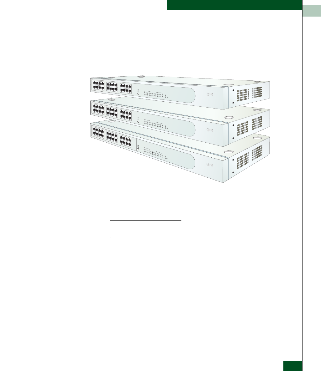
3. Stack the remaining hubs on top of the first hub as shown in
Figure 2-1. Ensure the adhesive rubber pads on the underside of a
hub align with the recesses on the top of the hub below.
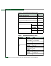
Figure 2-1 Stacked Ethernet Hubs
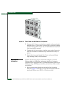
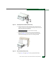
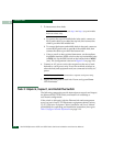
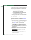
4. To interconnect three hubs:
NOTE: To connect two hubs, use step a and step c (top and middle
hub instructions only).
a. To connect the top and middle hubs in the stack, connect an
RJ-45 patch cable to port 24 of the top hub, then connect the
cable to port 12 of the middle hub.
b. To connect the bottom and middle hubs in the stack, connect a
second RJ-45 patch cable to port 24 of the middle hub, then
connect the cable to port 12 of the bottom hub.
c. Using a pencil or other pointed instrument, set the medium-
dependent interface (MDI) switch on the top and middle hubs
to MDI (in). Set the MDI switch on the bottom hub to MDIX
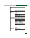
(out). The configuration is shown in Figure 2-2 on page 2-10.
®
3
com
1
2
3
4
6
7
8
9
10
11
12
22
23
24
21
20
19
18
17
16
15
14
13
Power
100M
Collision
Port Status
Green - 100M, Yellow- 10M, Flash - Activity
M
ID
Baseline
10/100
Hub
3C16411
S
uperStack
3
®
21
20
9
12
24
8
5
17
4
16
1
13
M
D
IX
10M
5
®
3
com
1
2
3
4
6
7
8
9
10
11
12
22
23
24
21
20
19
18
17
16
15
14
13
Power
100M
Collision
Port Status
Green - 100M
,
Yellow
- 10M, Flash -
Activity
MID
Baseline 10/100 Hub
3C16411
SuperStack3
®
21
20
9
12
24
8
5
17
4
16
1
13
MDIX
10M
5
®
3
com
1
2
3
4
6
7
8
9
10
11
12
22
23
24
21
20
19
18
17
16
15
14
13
Power
100M
Collision
Port Status
Green - 100M, Yellow
- 10M, Flash
-
Activity
MID
Baseline 10/100 Hub
3C16411
SuperStack3
®
21
20
9
12
24
8
5
17
4
16
1
13
MDIX
10M
5