


3
MAP 0100: Power Distribution Analysis
3-31
Diagnostics
• This procedure is concurrent and can be performed while the
switch is powered on.
• Perform the data collection procedure after FRU removal and
replacement.
Did power supply replacement solve the problem?
NO YES
↓ The switch appears operational.
Contact the next level of support.
11
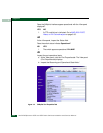
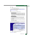
At the Product View, does a grey square appear at the alert panel and
as the background to the icon representing the switch reporting the
problem?
The grey square indicates the EFC Server cannot communicate with
the switch because:
• The switch-to-EFC Server Ethernet link failed.
• AC power distribution in the switch failed, or AC power was
disconnected.
• The switch’s CTP card failed.
YES NO
↓ The switch appears operational.
12
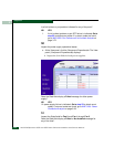
Ensure the power switch is set to the Power On (1) position. Inspect
the switch for indications of being powered on, such as:
• At the front panel, an illuminated PWR or ERR indicator.
• Green LEDs illuminated on the power supplies.
• Audio emanations and airflow from fans.
Does the switch appear powered on?
NO YES
↓ Analysis for an Ethernet link or CTP card failure is not
described in this MAP. Go to MAP 0000: Start MAP on
page 3-6. If this is the second time at this step, contact the
next level of support.