4
4-10
McDATA® Sphereon 3032 and 3232 Fabric Switches Installation and Service Manual
Repair Information
— PWR - power supply. Chassis slots for redundant power
supplies are 0 and 1. Power supplies are FRUs.
— FAN - cooling fan. Chassis slots for redundant fans are 0
through 3. Fans are FRUs.
— CTP - control processor (CTP) card. The chassis slot is 0. The
CTP card is not a FRU.
— THM - thermal sensor. The chassis slot is 0. The thermal
sensor is not a FRU.
• Position - a number representing the FRU chassis position.
Chassis slots for power supplies are 0 and 1. Chassis slots for fans
are 0 through 3 inclusive. Chassis slots for SFPs are 0 through 31.
• Action - the action performed (Inserted or Removed).
• Part Number - the part number of the inserted or removed FRU.
• Serial Number - the serial number of the inserted or removed
FRU.
Product Manager
Link Incident Log
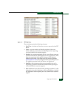
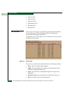
The Link Incident Log (Figure 4-5) displays a history of Fibre Channel
link incidents and associated port numbers for the switch. The
information is useful to maintenance personnel for isolating port
problems and repair verification.
To open the Link Incident Log, select Link Incident Log from the Logs
menu on the navigation control panel.


