


CHAPTER 2 V
R
4120A
134
Preliminary User’s Manual S15543EJ1V0UM
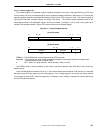
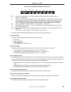
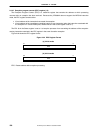
2.5.3.5 Status register (12)
The Status register is a read/write register that contains the operating mode, interrupt enabling, and the diagnostic
states of the processor. Figure 2-51 shows the format of the Status register.
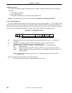
Figure 2-51. Status Register Format
29 28 27
26
25 24 16 15 8 7 6 5 4 3 2 1 031
0
CU0
0 RE DS IM KX SX UX KSU
ERL
1213 9
EXL
IE
8 111211 1
CU0 : Enables/disables the use of the coprocessor (1 → Enabled, 0 → Disabled).
CP0 can be used by the kernel at all times.
RE : Enables/disables reversing of the endian setting in User mode (0 → Disabled, 1 → Enabled).
Caution This bit must be set to 0.
DS : Diagnostic Status field (see Figure 2-52).
IM : Interrupt Mask field used to enable/disable external/internal and software interrupts (0 → Disabled, 1 →
Enabled). This field consists of 8 bits that are used to control eight interrupts. The bits are assigned to
interrupts as follows:
IM7 : Masks a timer interrupt.
IM (6:2) : Mask ordinary interrupts (Int (4:0)
Note
). However, Int4
Note
never occur in the V
R
4120A CPU.
IM (1:0) : Software interrupts.
Note Int (4:0) are internal signals of the CPU core. For details about connection to the on-chip
peripheral units.
KX : Enables 64-bit addressing in Kernel mode (0 → 32-bit, 1 → 64-bit). If this bit is set, an XTLB Refill
exception occurs if a TLB miss occurs in the Kernel mode address space.
In addition, 64-bit operations are always valid in kernel mode.
SX : Enables 64-bit addressing and operation in Supervisor mode (0 → 32-bit, 1 → 64-bit). If this bit is set,
an XTLB Refill exception occurs if a TLB miss occurs in the Supervisor mode address space.
UX: : Enables 64-bit addressing and operation in User mode (0 → 32-bit, 1 → 64-bit). If this bit is set, an
XTLB Refill exception occurs if a TLB miss occurs in the User mode address space.
KSU : Sets and indicates the operating mode (10 → User, 01 → Supervisor, 00 → Kernel).
ERL : Sets and indicates the error level (0 → Normal, 1 → Error).
EXL : Sets and indicates the exception level (0 → Normal, 1 → Exception).
IE : Sets and indicates interrupt enabling/disabling (0 → Disabled, 1 → Enabled).
0 : RFU. Write 0 in a write operation. When this bit is read, 0 is read.
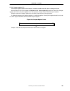
Figure 2-52 shows the details of the Diagnostic Status (DS) field. All DS field bits other than the TS bit are
writeable.