


CHAPTER 6 USB CONTROLLER
362
Preliminary User’s Manual S15543EJ1V0UM
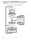
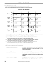
(b) Rx assemble mode
USB Controller sets EP2FO (EndPoint2 No Data) bit (Bit 9) in USB General Status Register 2.
USB Controller writes dummy data to Data Buffer (In fact, USB Controller only increment pointer which addresses
Data Buffer by Max Packet Size. No DMA transfer occurs) so that the sum of received data and dummy data becomes
equal to Max Packet Size.
After USB Controller receives “USB short packet”, USB Controller writes Rx indications which indicates that EP2
FIFO Overrun has occurred.
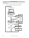
(c) Rx separate mode
USB Controller sets EP2FO (EndPoint2 No Data) bit (Bit 9) in USB General Status Register 2.
USB Controller writes dummy data to Data Buffer (In fact, USB Controller only increment pointer which addresses
Data Buffer by Max Packet Size. No DMA transfer occurs) so that the sum of received data and dummy data becomes
equal to Max Packet Size.
USB Controller writes Rx indications which indicates that EP2 FIFO Overrun has occurred.
6.6.10 Rx indication
For every data segment that it receives, USB Controller writes a receive indication into the receive MailBox. After
writing a receive indication, USB Controller sets the receive completion bit of the USB General Status Register to a ‘1’
and, issues an interrupt if it is not masked.
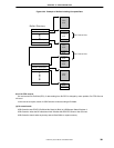
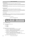
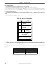
The format of the receive indication is as shown below.
Figure 6-26. Receive Indication Format
31 15 016
Status Size
Address
26
Reserved
25
EPN
30 29
Word1
Word2
28
Remark Bit28 to Bit26 are reserved.
EPN: Field that indicates the EndPoint number.
001: EndPoint0
011: EndPoint2
101: EndPoint4
111: EndPoint6
Status: Field that indicates the status upon data receiving.
Bit25: When set to a ‘0’, indicates that a data corruption did not occur on EndPoint2.
When set to a ‘1’, indicates that a data corruption occurred on EndPoint2.
Bit24: When set to a ‘0’, indicates that an internal bus error has not occurred.
When set to a ‘1’, indicates that processing terminated abnormally due to an internal bus error.
When this bit is set to 1, the Address field has no meaning.
Bit23: When set to a ‘0’, indicates that the received data is other than a USB Setup packet.
When set to a ‘1’, indicates that the received data is a USB Setup packet.
This bit is set only when receiving the data from the Control EndPoint (EndPoint0). If data is
received from any other EndPoint, this bit is not set.
Bit22: When set to a ‘0’, indicates that a buffer overrun did not occur.