


CHAPTER 2 V
R
4120A
Preliminary User’s Manual S15543EJ1V0UM
89
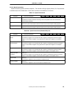
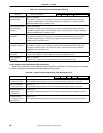
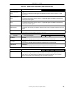
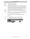
2.3.4.2 Jump and link register instruction (JALR rd, rs)
IF stage Same as the IF stage for the ADD instruction.
IT stage Same as the IT stage for the ADD instruction.
RF stage A register specified in the rs field is read from the file during
Φ
2 at the RF stage, and the value
read from the rs register is input to the virtual PC latch synchronously. This value is used to
fetch an instruction at the jump destination. The value of the virtual PC incremented during the
IF stage is incremented again to produce the link address PC + 8 where PC is the address of
the JALR instruction. The resulting value is the PC to which the program will eventually return.
This value is placed in the Link output latch of the Instruction Address unit.
EX stage The PC + 8 value is moved from the Link output latch to the output latch of the EX stage.
DC stage The PC + 8 value is moved from the output latch of the EX stage to the output latch of the DC
stage.
WB stage Refer to the ADD instruction. Note that if no value is explicitly provided for rd then register 31 is
used as the default. If rd is explicitly specified, it cannot be the same register addressed by rs;
if it is, the result of executing such an instruction is undefined.
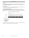
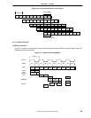
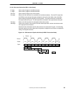
Figure 2-14. JALR Instruction Pipeline Activities (In MIPS III Instruction Mode)
IF1
Cycle
Phase
PCycle
PClock
IF2
Φ
2
Φ
1
Φ
2
Φ
1
Φ
2
Φ
1
Φ
2
Φ
1
Φ
2
Φ
1
RF1 RF2 EX1 EX2 DC1 DC2 WB1 WB2
ITLB
IDC
ITC
ICA
IDEC WBEX
BAC
RF