


CHAPTER 7 PCI CONTROLLER
Preliminary User’s Manual S15543EJ1V0UM
407
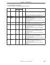
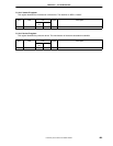
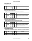
7.5.19.10 Header type register
This register identifies the layout of the second part of the predefined header and also whether or not the device
contains multiple functions.
R/WBits Field
Internal
bus
PCI
Default Description
7:0 Header Type R R 0 Hardwired to ‘00H’, because the PCI Controller is a single
function device and not a PCI-PCI bridge.
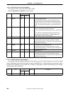
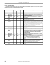
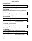
7.5.19.11 Window memory base address register
This register specifies the base address of the PCI Memory space for the access window.
R/WBits Field
Internal
bus
PCI
Default Description
31:0 Window
Memory Base
Address
R/W
(upper
10 bits)
R
(lower
22 bits)
R/W
(upper
10 bits)
R
(lower
22 bits)
0 Memory Base Address for the access window.
Not all bits in this register are writeable. The lower 22 bits are
hardwired to ‘0’ in order to indicate that the area with 2 MB is
required in the 32-bit Memory Space.
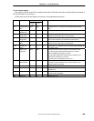
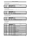
7.5.19.12 Register memory base address register
This register specifies the base address of the PCI Memory space for the registers.
R/WBits Field
Internal
bus
PCI
Default Description
31:0 Register
Memory Base
Address
R/W
(upper
20 bits)
R
(lower
12 bits)
R/W
(upper
20 bits)
R
(lower
12 bits)
0 Memory Base Address for the I/O registers.
Not all bits in this register are writeable. The lower 12 bits are
hardwired to ‘0’ in order to indicate that the area which size is
4 KB is required in the 32-bit Memory Space.
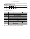
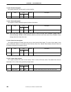
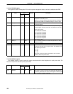
7.5.19.13 Subsystem vendor ID register
This register is used to uniquely identify the manufacturer of the expansion board or subsystem where the PCI
device resides.
R/WBits Field
Internal
bus
PCI
Default Description
15:0 Subsystem
Vendor ID
R/W R 0 The V
R
4120A should set the identifier to this register.