


CHAPTER 6 USB CONTROLLER
342
Preliminary User’s Manual S15543EJ1V0UM
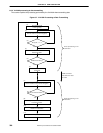
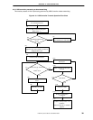
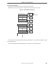
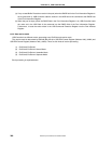
Numbers (1) to (15) do not indicate the order in which USB Controller must perform processing. Instead, these
numbers correspond to those in the following explanation.
(1) USB Controller starts transmit processing upon receiving a transmit command from the V
R
4120A.
(2) When the command is written, USB Controller sets the Busy bit in USB Command Register to a ‘1’.
(3) USB Controller checks whether the EndPoint specified with the transmit command is currently in the Busy
status (two data are scheduled to be transmitted).
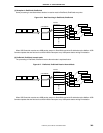
(4) If the EndPoint specified with the transmit command is found to be in the Busy status, the command written
at (1) is not executed until the specified EndPoint can accept a new Tx command.
(5) The command written into the USB Command Register and USB Command Extension Register in (1) is
copied to an internal register and the Busy bit of the USB Command Register is returned to a ‘0’.
(6) USB Controller reads the buffer descriptor.
(7) USB Controller compares the size of the area remaining in the Tx FIFO with the buffer size of the buffer
descriptor read in the previous step.
(8) If step (7) reveals that the area remaining in the Tx FIFO is smaller, USB Controller transfers the data from
the buffer until the Tx FIFO is full by DMA.
(9) Once the Tx FIFO is full, USB Controller transfers the data to the USB.
(10) If step (7) reveals that the area remaining in the Tx FIFO is larger, USB Controller transfers all the data in
the buffer to the Tx FIFO by DMA.
(11) USB Controller checks whether the data transferred by DMA is the last data of the data segments to be
transmitted to a Host.
(12) If the data transferred by DMA is not the last to be transmitted, it indicates that the buffer is empty.
Therefore, USB Controller reads the next buffer descriptor.
(13) If the data transferred by DMA is the last to be transmitted, USB Controller transmits the data.
(14) USB Controller writes a Tx indication in the MailBox.
(15) USB Controller updates the MailBox write pointer (USB Tx MailBox Write Address Register). It also sets the
transmit finish bit of the USB General Status Register 1, and if it is not masked, issues an interrupt to the
V
R
4120A.