


CHAPTER 2 V
R
4120A
Preliminary User’s Manual S15543EJ1V0UM
99
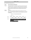
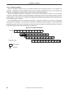
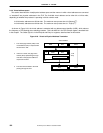
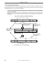
Figure 2-24. MD Busy Interlock
1
MFLO/MFHI
Bypass
Detect MD busy interlock
IF RF EX DC WB
IF RF RF EX DC WB
IF RF EX DC WB
1
Get target data2
2
MD Busy Interlock is detected in the RF stage as shown in Figure 2-24 and also the pipeline slips in the stage. MD
Busy Interlock occurs when HI/LO register is required by MFHI/MFLO instruction before finishing Mult/Div execution.
The pipeline begins running again the clock after finishing Mult/Div execution. The data returned from the HI/LO
register at the end of the DC stage is input into the end of the RF stage, using the bypass multiplexers.
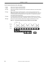
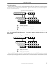
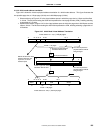
Store-Load Interlock is detected in the EX stage and the pipeline slips in the RF stage. Store-Load Interlock occurs
when store instruction followed by load instruction is detected. The pipeline begins running again one clock after.
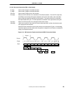
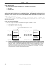
Coprocessor 0 Interlock is detected in the EX stage and the pipeline slips in the RF stage. A coprocessor interlock
occurs when an MTC0 instruction for the Configuration or Status register is detected.
The pipeline begins running again one clock after.
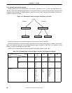
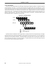
2.3.5.4 Bypassing
In some cases, data and conditions produced in the EX, DC and WB stages of the pipeline are made available to
the EX stage (only) through the bypass data path.
Operand bypass allows an instruction in the EX stage to continue without having to wait for data or conditions to be
written to the register file at the end of the WB stage. Instead, the Bypass Control Unit is responsible for ensuring
data and conditions from later pipeline stages are available at the appropriate time for instructions earlier in the
pipeline.
The Bypass Control Unit is also responsible for controlling the source and destination register addresses supplied
to the register file.