


CHAPTER 6 USB CONTROLLER
344
Preliminary User’s Manual S15543EJ1V0UM
6.6 Data Receive Function
This section explains USB Controller's data receive function.
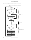
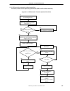
6.6.1 Overview of receive processing
USB Controller receives USB packets from the USB, stores them into system memory, and then assembles a
single data segment. The V
R
4120A sets the size of a single USB packet in the MAXP field of the EP0 Control
Register, EP1-2 Control Register, EP3-4 Control Register, and EP5-6 Control Register. (The figure shown below is an
example when the packet size is set to 64 bytes.)
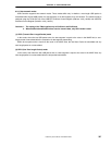
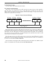
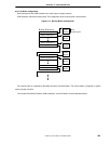
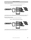
Figure 6-12. Division of Data into USB Packets
Data Segment
USB
Packet
USB
Packet
USB
Packet
USB
Packet
USB
Packet
64 Bytes 64 Bytes 64 Bytes 64 Bytes 40 Bytes
When the data segments are divided to USB packets with the same byte size as a value set in the MAXP field, the
last USB packet of the data segment will be smaller than the value set in the MAXP field (40 bytes in the example
shown above). As a result, USB Controller can identify the boundary between data segments. If the last USB buffer
size is equal to the value in the MAXP field, a zero-length USB packet will be transmitted from the Host PC to USB
Controller after the last USB packet of the data segment.
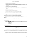
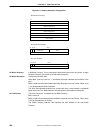
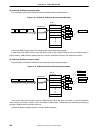
When placing data received from the USB to system memory, an area to store received USB packet is required in
system memory. This area is referred to as the Rx buffer. It must be secured by the V
R
4120A. For an explanation of
the Rx buffer, see Section 6.6.2 Rx Buffer configuration.
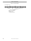
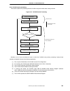
Upon the completion of data segment transfer, USB Controller writes the "Rx indication" into a MailBox in system
memory. For an explanation of the Rx modes, see Section 6.6.4 Data receive mode.