


CHAPTER 7 PCI CONTROLLER
Preliminary User’s Manual S15543EJ1V0UM
393
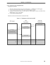
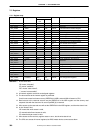
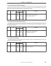
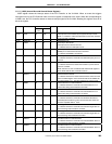
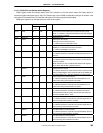
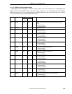
7.5.7 P_IGSR (Internal Bus-side General Status Register)
IGSR register shows the interrupt status of the PCI Controller to the V
R
4120A. When an event that triggers
interruption occurs, the PCI Controller sets a bit in this register corresponds to the event. When the corresponding bit
in IIMR is set, the PCI Controller asserts an internal interrupt signal to the V
R
4120A. Reading this register clears all of
bits in the register.
R/WBits Field
Internal
bus
PCI
Default Description
31:16 IUINT R R/W 0 Interrupts that can be defined by the system the chip is used.
When ‘1’ is written to a bit in this field from PCI bus side, interrupt
to the V
R
4120A is asserted.
15:12 Reserved - - 0 Hardwired to ‘0’s.
11 PINTR R R 0 Used only in Host-mode.
Interrupts from PCI-device occurred.
‘1’ indicates that a PCI-interruption occur.
10 PSERI R R 0 Used only in Host-mode.
SERR_B from external PCI-devices is asserted.
‘1’ indicates that SERR_B is asserted.
9 PPERR R R 0 PCI Parity Error.
‘1’ indicates that the PCI Controller has detected a parity error on
PCI bus.
8 PPREQ R R 0 The transition of PPMI Power state issued.
‘1’ indicates that PCI-Host issues the transition of power state of
The PCI Controller.
When this bit is set, the V
R
4120A should check PPCR register to
know which state the PCI Controller moves to.
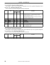
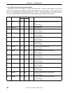
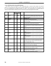
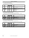
7 SRREQ R R 0 Software Reset is issued.
‘1’ indicates that PCI-Host issues Software Reset, when PCI-Host
writes to SWRS register. the V
R
4120A should be set SWRDN bit
in PGSR register to a ‘1’ after the completion of software reset.
6 IRBER R R 0 Internal bus Error in read transaction.
‘1’ indicates that the PCI Controller has received Bus Error on
internal bus during read transaction as master.
5 IWBER R R 0 Internal bus Error in write transaction.
‘1’ indicates that the PCI Controller has received Bus Error on
internal bus during write transaction as master.
4 IFDSC R R 0 Internal bus FIFO data discarded.
‘1’ indicates that the PCI Controller has discarded the data for
read-delayed-transaction in FIFO, because the same issue has
not been repeated within 2
15
clock.
3 RDTAT R R 0 PCI Target Abort in read transaction.
‘1’ indicates that the PCI Controller has received Target Abort on
PCI bus during read transaction as master.
2 WRTAT R R 0 PCI Target Abort in write transaction.
‘1’ indicates that the PCI Controller has received Target Abort on
PCI bus during write transaction as master.
1 RDMAT R R 0 PCI Master Abort in read transaction.
‘1’ indicates that the PCI Controller has received Master Abort on
PCI bus during read transaction as master.
0 WRMAT R R 0 PCI Master Abort in write transaction.
‘1’ indicates that the PCI Controller has received Master Abort on
PCI bus during write transaction as master.